2-10
CDD3000-HF Operation Manual
2 Mechanical installation
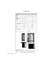
CDD3...-HF,Dx.x
BG3
BG4
BG5
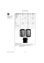
Weight [kg]
4.6
6.7
7.4
B (width)
110
160
210
H (height)
340
D (depth)
T1 138, T2 80
T1 138, T2 135
A
90
140
190
A1
–
80
100
C
320
C1
200
D
∅
∅
4.8
∅
4.8
∅
4.8
Screws
8 x M4
10 x M4
10 x M4
E
1)
10
E1 (with module)
1)
10
F
1)
100
2)
G
1)
> 300
1) Mounting clearances, see Figure 2.3
2) Additionally allow enough space at the bottom for the bending radii of the connecting cables.
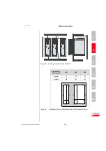
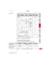
Table 2.5
Dimensional drawings: push-through heat sink
(dimensions in mm)
A
C1
C
D
∅
T1
T2
B
H
BG3
A1
A
C1
C
D
∅
B
H
BG4
BG5
X5
X6
X7
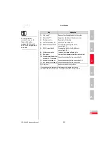
For further ambient
conditions,
see appendix A.2

