CDD3000-HF Operation Manual
3-27
3 Installation
DE
EN
FR
IT
ES
FR
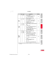
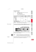
Electrical specification
Interface:
RS422
Recommended wire cross-section >0.14 mm²
(e.g. 3x2x0.14 mm²)
Max. cable length 10 m
Connector: 9-pin D-SUB, socket
HTL master encoder
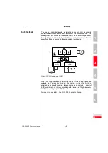
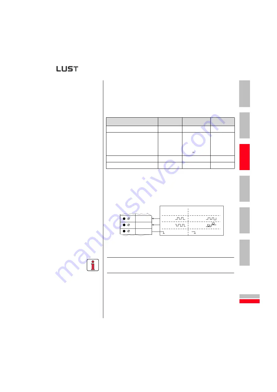
A master encoder with HTL level (24V) can alternatively be connected via
control terminal X2. Digital inputs ISD03 and ISD04 are used for this.
You will find the specification of the digital inputs of control terminal X2 in
section 3.6 "Control connections".
Note:
When a HTL master encoder is in use, both the encoder
simulation and the master encoder input at X5 are inactive.
TTL encoder
A rotary encoder with TTL level can also be connected to master encoder
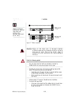
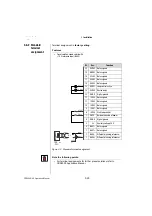
input X5. For the terminal assignment refer to Figure 3.13 .
min.
max.
Type
Input frequency
0 Hz
500 kHz
Input voltage
•
High level
•
Low level
•
Differential
0.2 V
-
- 0.2 V
+ 6 V
Wave terminating resistance
120
Ω
Voltage supply to external encoder
4.5 V
5.5 V
5 V / 100 mA
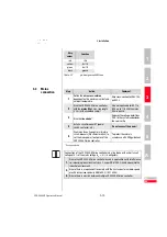
Table 3.10
Master encoder input electrical specification
ISD03
ISD04
DGND
Incremental
Stepper motor interface
X2
GND
Track A
Track B
Direction
Clock
CNC or HTL master encoder
GND
11
12
13

