CDD3000-HF Operation Manual
3-23
3 Installation
DE
EN
FR
IT
ES
FR
3.8
Encoder
simulation -
Master encoder
input
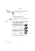
The plug connection X5 of the CDD3000-HF drive controller is designed
alternatively to provide the
•
incremental encoder simulation or
•
incremental master encoder input
function. The signals are isolated from the control electronics.
3.8.1 Encoder
simulation
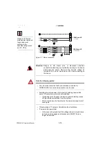
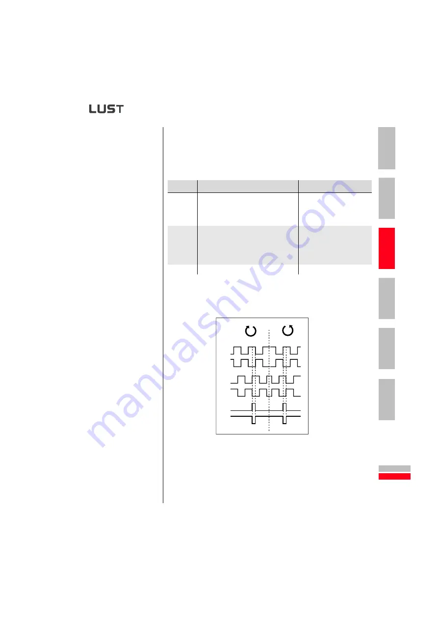
Encoder simulation forms incremental encoder-compatible pulses from
the position of the rotary encoder connected to the motor. Accordingly,
pulses are delivered in two 90° offset signals A and B as well as a zero
pulse R.
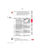
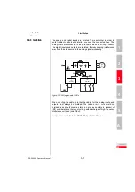
Figure 3.11 Encoder simulation signals looking onto the motor shaft (at left
when motor rotating clockwise)
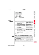
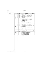
Step
Action
Comment
1
Define the
function
of the connection:
•
Encoder simulation
•
Master encoder input
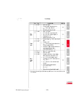
2
Specify the wire according to the
application. A wire cross-section of less than
0.14 mm² should not be chosen. The
differential signals (A, B and R) must be
connected to twisted pair wires.
Mount shield at both ends to
reduce interference emission
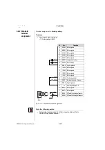
3
Wire the circuit according to the application
A+
A-
B-
B+
R+
R-


