14
0697-401 Pump
werke - 04/2021
en
10.3 Special conditions
►
Ensure that additional fitted components
(e.g. coupling, gear, drive motor) are located
outside of the mobile container.
►
The requirements of unit group II (sub-class II
B), category 2, temperature class T4 have to be
met.
►
Ensure that the drive motor (electrical or with
compressed air) does not exceed an output of
0.88 kW and a speed of 17,000 1/min.
►
Do not use the drum pump for stationary
operation.
►
The operation of the pump has to be
monitored during the pumping process in
order to avoid dry running and empty running
phases.
10.4 Equipotential bonding and
earthing
►
Before starting up, an equipotential bonding
must be established between the pump, the
container to be emptied and the container to
be filled.
►
Clamp the equipotential bonding cable (order
no. 0204-994) to create an equipotential
bonding between the pump and the container
to be emptied. For better conductivity, remove
the paint and dirt from the clamping points.
►
Equipotential bonding between the containers
to be emptied and to be filled via a conductive
substrate (e.g. conductive gratings).
►
Ensure that a conductive transition between
container and earthing potential is available.
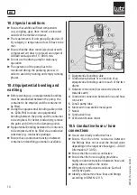
8
9
1
Equipotential bonding cable
2
Conductive substrate or connection of an
equipotential bonding cable to each of the two
drums
3
Galvanic connection (low contact resistance
towards earth)
4
Conductive connection between hose and hose
connector
5
Zone 0 pump tube
6
Motor with inaccessible metal parts
7
Nozzle
8
Conductive hose
9
ATEX-identification motor
10.5 Conductive hoses / hose
connections
►
Use an electrically conductive hose.
►
Ensure that the ohmic resistance between
the fittings does not exceed the limited value
depending on the respective hose type (
→
DGUV
Information 213-053).
►
Ensure that the nozzle is conductive.
►
Ensure that the hose coupling provides a
highly conductive transition between hose and
pump tube as well as the nozzle.
►
With poorly conductive transitions: Earth all
conductive parts.
►
Identify and examine hose lines and fittings
according to DIN EN 12115.
Summary of Contents for Alu 41-L-DL
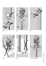
Page 2: ...Fig 1 Fig 5 Fig 3 Fig 2 Fig 4 Fig 6 Pump tube RE SS 0697 401 Pumpwerke 04 2021...
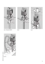
Page 3: ...Fig 8 Fig 9 Fig 10 Fig 7 Pump tube RE PP 3 0697 401 Pumpwerke 04 2021...
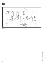
Page 4: ...Fig 11 4 0697 401 Pumpwerke 04 2021 en...
Page 20: ...20 0697 401 Pumpwerke 04 2021 en...

