perfect measures against possible
internai DC drifts have been in
tegrated. However, leakage of DC
ingredient from other audio com
ponent which is connected to
this amplifier may be unavoidable.
Such leakage will cause malfuntion
ing of the amplifier, then speakers,
being fed with amplified DC ingredi
ents, may be affected or in worst
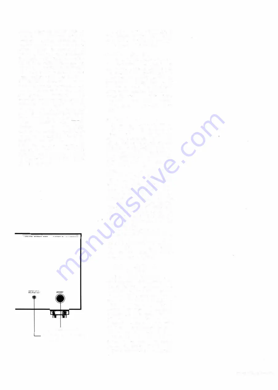
cases, broken down. The DC OFF
SET SENSOR is added to the cir
cuitry to monitor existence of any
harmful DC ingredients at the out
put terminais. The SENSOR lamp
serves bilaterally, as the power pilot
lamp and the SENSOR light. The
lamp continues to light up in white
while no DC ingredient is fed to the
input terminais of the amplifier.
When ± 450mV or more voltage
appears at the output terminais,
color of the SENSOR light changes
to red to give warning that DC in
gredients are fed from exterior
audio components.
When such
warning is made, lift the INPUT
CAPACITOR IN/OUT SELECTOR
(7) to select the "INPUT CAPA
CITOR" position.
5. POWER SWITCH
4. DC OFFSET SENSOR
/PILOT LAMP
And the harmful DC ingredients
are blocked at the input, when
color of the light returns to white
within two or three seconds.
5. POWER SWITCH
This switch is for push-ON, push
OFF operation. To press in the
switch, AC power is supplied and
the pilot lamp (4) begins to blink
which lasts for 5
~
20 seconds. As
soon as the amplifier is warmed up
for normal operating condition,
white lamp indication stays. Simul
taneously the VU meter lamps
illuminate. To switch off the am
plifier. press in the switch once
again.
6. INPUT TERMINAL$
Outputs of the mating control
(pre) amplifier are connected to
these terminais. Next to these
terminais, independent attenuators
(8) for the both channels are pro
vided to permit flexible regulation
of input sensitivity. The maximum
input sensitivity of the terminais is
890mV, and the input impedance is
50K ohms.
This means the
maximum gain is obtainable by
input signal level of 890mV when
the INPUT ATTENUATOR (8) is
set at the MAX. position (com
pletely turned clockwise). Input
sensitivity can be continuously
decreased by turning of the
ATTENUATOR to the counter
clockwise direction. At the extreme
counter-clockwise end position (00),
input sensitivity is eut to zero and
no audio signal is available from the
output terminais.
Since the B-type variable resistor
is used for the attenuators, at the
central (neutral) point of the at
tenuator knob, sensitivity attenua
tion is 6dB from the maximum
level and input sensitivity of this
amplifier becomes 1 .78V.
7. INPUT CAPACITOR IN/
OUT SELECTOR
Since DC amplification is a
dopted, when any DC ingredients are
fed to the input terminais of this
amplifier from an external source,
amplified DC ingredients will corne
out from the output terminais re
sulting in abnormal function of
speakers, actuation of protective
circuits, etc. To avoid such im
pediment, the DC OFFSET
SENSOR is provided to give visible
warning. The pilot/warning lamp
(4) that normally lights in white
turns to red when DC ingredients
are sensed. As soon as the warning
is given. set this SELECTOR. which
is provided subsequent to the input
3


