Operation Procedure
Upon accomplishment of all the
preparations described in the "CON
N ECTION PROCEDURE" in this
manual. playback of program
sources can be made through th is
amplifier. However the following
procedure is further necessary to
drive the amplifier under its best
operating condition.
1. Turn the ATTENUATOR knobs
(8) to the complete counter-clock
wise end to set them at the MIN.
position. Also completely turn the
volume control knobs of the mating
preampl ifier counter-clockwise to
eut off the output.
2. Turn on the power switches of
the preamplifier and this amplifier.
Almost all current models of am
plifier are so designed that during
warming up, the output circuit is
isolated which is normally referred
to as the muting time. The muting
time of this amplifier is 5
~
20
seconds and during this period, the
DC OFFSET SENSOR/PILOT
LAMP (4) gives blinking indication.
After the muting time, the lamp
continues to illuminate to indicate
the amplifier is standing by for
playback operation. lt is necessary
'
-
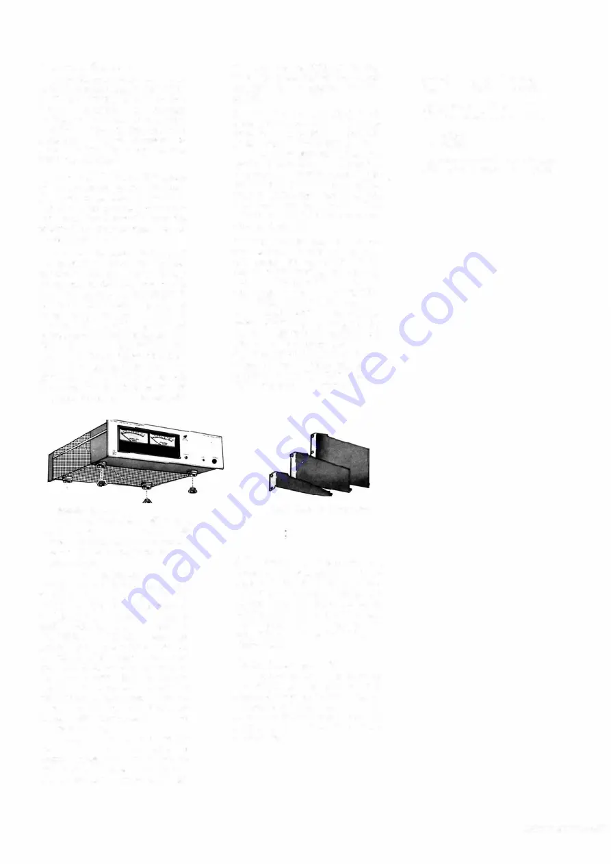
Attached leg caps
The illustration is for the 5M21 power
amplifier, but ail the models in Labo•
ratorv Reference Series adopt the same
construction for smooth placement.
About Legs
·-
Ali the components in our
Laboratory Reference Series are
provided with the legs at the
bottom and the metalic receptacles
on the top, and metalic suppart is
placed between the leg and its
receptacle. Thus you need not
worry about breakage caused by
an accumulated weight even when
they are stacked one by one, as
the total weight is given to the
legs of the very unit placed at
the bottom of such stack. Perfect
fit between the legs and receptacles
prevents each component unit from
falling or sliding.
However if the unit is placed on
the furniture or other kind of
wooden cases, with these legs as
they are, it is passible to cause a
slip or scratch. To prevent this,
that the input selector of the pre
amplifier is selected at the correct
position for a desired program
source.
3. Turn the ATTENUATOR (8)
knobs (for the both channels) of this
amplifier completely clockwise
to set them at the MAX. position.
Then turn the preamplifier volume
control clockwise until appropriate
playback volume is obtained. When
the output level of preamplifier
falls to be too high, regulation can
then be made by the ATTENU
A TOR (8) by turning the knobs
counter-clockwise.
4. When the playback level is low
and the amplifier is driven for out
put power far below its rating,
meter needle reading of the VU
METER may be difficult. ln such
case press in the METER SENSI
TIVITY SELECTOR (2) to set it at
the - 1 0dB position. By this the
meter sensitivity is boosted by
1 0dB. Relationship between dB
(decibel) calibration on the METER
and the POWER OUTPUT is des
cribed in the "RMS output level"
described in the "ON POWER OUT
PUT" section of this ma nuai.
Rack Mount Adapters
4
·
Ieg caps of synthetic resin are
provided as accessories.
When
some of the components in our
Laboratory Reference Series are
stacked, the leg caps should be
attached to the legs of the last
unit placed at the bottom of
such stack. To fix them refer to
the drawing.
About Rack-Mounting
ln order to mount the 5M21 or
the 5M20 to the rack of EIA
standard, adapters are available on
request. Note that the size of the
adapter varies from one product to
another in our Laboratory Refer
ence Series.
OPERATION
PROCEDURE
LEGS
RACK-MOUNTING
9


