Phone: +1 (949) 654-2047
Address: Irvine, CA, USA
Document name: AMP-1002 quick start guide
Revision: 1.05
Date: 7/31/2020
US and PCT patents pending
Specifications are subject to change without notice
the product.
Wrong type of screw could strip the threads; too long screw could touch and short the
internal circuit, cause permanent damages to the product and void the warranty.
Control options:
The product has two
recessed gain pots on the front panel,
one loudness control dip switch recessed
on the bottom of the unit, and a remote
volume control port on the rear panel.
The Line Gain pot controls the mixed 3
line input levels. The Mic Gain pot
controls the mic input levels. The
volume control only controls the volume
of the mixed 3 line input levels; it can
also be used for PA emergency mute.
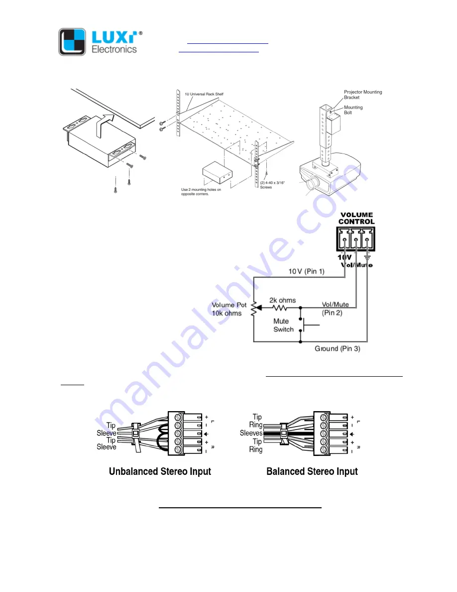
See the external volume control and
mute circuit diagram to the right of here.
Audio input connector wiring:
You can
use the standard 3.5 mm cable to
connect to input No 2 thru 4. The captive
screw connector for input No. 1 is
provided with the product. Follow the instructions on page 1 to cut the audio cable to needed length,
remove the overall cable jacket, separate the individual wires, strip off the wire insulation precisely 3/16”
(5 mm) from the end, and follow the wiring diagram below based on unbalanced or balanced input. In
unbalanced wiring, remember to use short jumper to connect pin 2 and 5 to pin 3 (ground the unused “-
“ inputs).
Speaker connector wiring:
Follow the instructions on page 1 to cut the audio cable to needed length,
separate the individual wires, strip off the wire insulation precisely 3/16” (5 mm) from the end.
Important note: this is a bridged power amp, all 4 pins of this speaker connector are live and none of
them can be connected to ground or between each other. When connecting to a subwoofer with
speaker level summer and filter, check the resistance between the subwoofer’s “-“ side of the left and


