background image


LX496 

V. 01 – 30/07/2014 

©Velleman nv 

7.


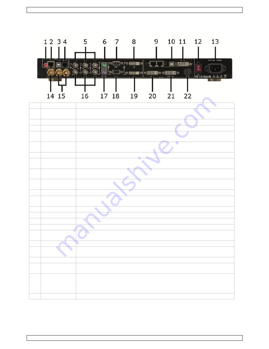
Hardware Overview 

7.1


Rear Panel 


No.  Name on panel  Description 

DIP switches 

For normal operation, make sure the dip switches are in the upper position. Used 
for IP software download/installation/upgrade. 

LAN 

8P8C 10/100 Mbps UDP interface. 

USB 

USB interface to connect to a computer. 

RS232 

6P6C (RJ11) connector to connect a computer via RS-232. You will need an 
adapter cable (not incl.). 

CV1-3 

Composite video BNC input ports 1–3. Support video signals from players, 
cameras, etc. Supports PAL, NTSC and SECAM. 

S-VIDEO 

mini-DIN-4 S-Video input port. Supports PAL, NTSC, and SECAM. 

VGA 

15-pin D-sub VGA connector for VGA input signals. Compatible with component 
YPbPr signals. 

DVI 

DVI input port for sending card. To connect the DVI output from another video 
processor. This connection does not support hot plugging. 


8P8C 10/100Mbps interface to connect an LED  power supply jack for 
sending card. 

10 


USB control port for sending card. 

11 

DVI IN 

DVI input port for sending card. To connect the DVI output from another video 
processor. This connection does not support hot plugging. 

12 

ON-OFF 

On/off switch. 

13 

AC 85-264V 

Power cord connector. 

14 

SDI LOOP 

BNC output port to another SDI input. 

15 

SDI1-2 

BNC input ports receiving signal from an HD player or camera. 

16 

CV1-3 

Composite video BNC output ports 1–3. Support video signals from players, 
cameras, etc. Supports PAL, NTSC and SECAM. 

17 

S-VIDEO 

mini-DIN-4 S-Video output port. Supports PAL, NTSC, and SECAM. 

18 

VGA 

15-pin D-sub VGA connector for VGA output signals. Compatible with component 
YPbPr signals. 

19 

DVI 

Connection to another LX496 or any device with DVI input. 

20 

DVI1 

DVI (DVI-I) output to a monitor or LED screen that supports DVI. This connector 
does not support hot plugging. 

21 

DVI2+VGA 

DVI+VGA output connector (DVI-I). To connect to a monitor or LED screen that 
supports DVI or VGA interfacing. $$$ This connector does not support hot 
plugging. To connect to a VGA interface, you need a DVI-to-VGA adapter (not 
incl.). 

22 

CVBS 

Output connection to another CVBS input. 


Summary of Contents for LX496

Page 1: ...LX496 2 LAYER SWITCHER AND SCALER USER MANUAL ...

Page 2: ...LX496 V 01 30 07 2014 2 Velleman nv Menu Structure ...

Page 3: ...alled Warning If the supply cord is damaged it must be replaced by the manufacturer its service agent or similarly qualified persons in order to avoid any hazard Make sure that the available voltage does not exceed the voltage stated in the specifications in this manual Always disconnect mains power when device not in use or when servicing or maintenance activities are performed Handle the power c...

Page 4: ...lity high resolution video presentation The LX496 is designed to deliver advanced capabilities to high end presentation environments 3G HD SD SDI input 1 composite 1 S Video input 1 component input VGA input support RGBHV RGBS RGSB 1 DVI input support 1080p video and 1600 x 1200 HDMI 1 3 compatible input support video and graphic input 1 DisplayPort DP input 5 audio inputs 1 DVI and 1 VGA output 1...

Page 5: ...plug should always remain readily operable Unplug the power supply cord from the mains to disconnect the device The environment where you install the device shall be clean properly lit free from static and have adequate power ventilation and sufficient space for all components Installation The LX496 video scan convertor and scaler is designed to be rack mounted Before mounting this device make sur...

Page 6: ... sending card 10 USB control port for sending card 11 DVI IN DVI input port for sending card To connect the DVI output from another video processor This connection does not support hot plugging 12 ON OFF On off switch 13 AC 85 264V Power cord connector 14 SDI LOOP BNC output port to another SDI input 15 SDI1 2 BNC input ports receiving signal from an HD player or camera 16 CV1 3 Composite video BN...

Page 7: ...l keys are described in detail below Display 23 Menu Keys 24 POSITION Image position adjustment SCALE Rescale the video image MENU Main menu access PIP Picture in picture single picture image Input Keys 25 CV1 CV3 Corresponds with the CV1 CV3 connectors 5 SVIDEO Corresponds with the SVIDEO connector 6 VGA Corresponds with the VGA connector 7 DVI Corresponds with the DVI connector 8 SDI1 SDI2 Corre...

Page 8: ...POSITION and set POS X and POS Y 5 Press MENU to return and exit the settings 8 4 Realizing Picture In Picture PIP Images Selecting the Primary and Secondary Images 1 Press the button corresponding to your primary image source 2 Press PIP to select the picture in picture function 3 Select your secondary image select an image source different from your primary image source Setting Size and Position...

Page 9: ...t resolutions to choose from 3 Select the desired output resolution and the resolution will be updated automatically 9 3 Switching the Input Signal 1 Select the INPUT icon in the taskbar 2 Select the desired signal source 9 4 Setting the Image Size and Position 1 Select the IMAGE icon in the taskbar 2 Modify the parameters with or 3 Click SET to confirm ...

Page 10: ...ith the left mouse button and slide to the right to activate the PIP function 3 Next choose the position of your secondary image Click the MODE tab 4 Choose the desired picture location PIP Top Left POP Picture Outside of Picture meaning 2 pictures side by side or PBP Picture by Picture meaning side by side display from 2 different video sources ...

Page 11: ...ding tab in the taskbar Note The PIP function will display the same image if Image1 and Image2 have the same video input source 9 6 Saving and Recalling Parameters 1 Select the SAVE icon in the taskbar 2 Select the desired USERMODE by clicking the corresponding bullet 3 You can now save SAVE or recall CALL parameters 9 7 Other Settings 1 Select the SETTING icon in the taskbar ...

Page 12: ...tive after rebooting To do so click the REB button 5 Proceed in the same way to modify the IP address IP 6 Also lock or unlock the function keys KEYLOCK and set the alpha transparency level DIMMER if desired 10 Troubleshooting Problem Possible Solution No output image Check your input signal Please check that your input device is properly connected and configured ...

Page 13: ...ance 75 ohm horizontal frequency autoscan 15 kHz to 100 kHz vertical frequency autoscan 50 Hz to 120 Hz resolution range autoscan 640 x 480 to 2048 x 1152 video processing encoder 10 bit digital digital sampling 30 bit 10 bit per colour 165 MH standard colours 16 78 million horizontal filtering 3 levels vertical filtering 3 levels encoder filtering 3 levels video output signal type 2 DVI 1 VGA 1 c...

Page 14: ...n shocks falls dust dirt humidity and by the article as well as its contents e g data loss compensation for loss of profits consumable goods parts or accessories that are subject to an aging process during normal use such as batteries rechargeable non rechargeable built in or replaceable lamps rubber parts drive belts unlimited list flaws resulting from fire water damage lightning accident natural...

Reviews: