R
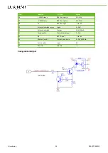
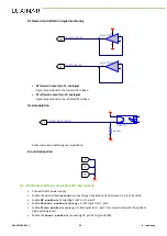
5-24V
Inactive: 5–24V
Active: 0V
Figure 23 - Typical open drain output connection
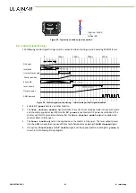
8.4. Control signal timings
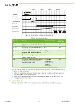
The following control signal timings must be respected when starting up and operating SR AOM lasers.
DC power
Interlocks
User shutter enable
Shutter position
RF enable
Laser enable
Output power
AOM demand
0
100ms
200ms
300ms
400ms
Figure 24 - Control signal startup timing — Initial startup with all signals disabled
1.
Enable
DC power
before any other function.
2.
The
User shutter enable
signal will take the system from standby mode into execute mode
and should be applied at least 80ms after
DC power
is enabled and DC power has stabilised. The
shutter will start to open immediately after the
User shutter enable
signal is applied and
requires 80ms to fully open.
3.
The
Laser enable
signal can be applied once the shutter is fully open. The laser output power
into the AOM module then requires 200ms to stabilise before applying the
AOM demand
signal.
4.
If required,
Interlocks
and
RF enable
signals can be applied before enabling
DC power
, as
shown in the following timing diagram.
906-0227-00 REV 1
41
8. Interfacing
Summary of Contents for SR 10 AOM
Page 1: ...USER MANUAL SR AOM series Sealed CO2 laser sources with integrated AOM...
Page 8: ...Preface iv 906 0227 00 REV 1...
Page 40: ...6 Installation 32 906 0227 00 REV 1...
Page 42: ...7 Transport and recommissioning 34 906 0227 00 REV 1...
Page 52: ...8 Interfacing 44 906 0227 00 REV 1...


