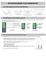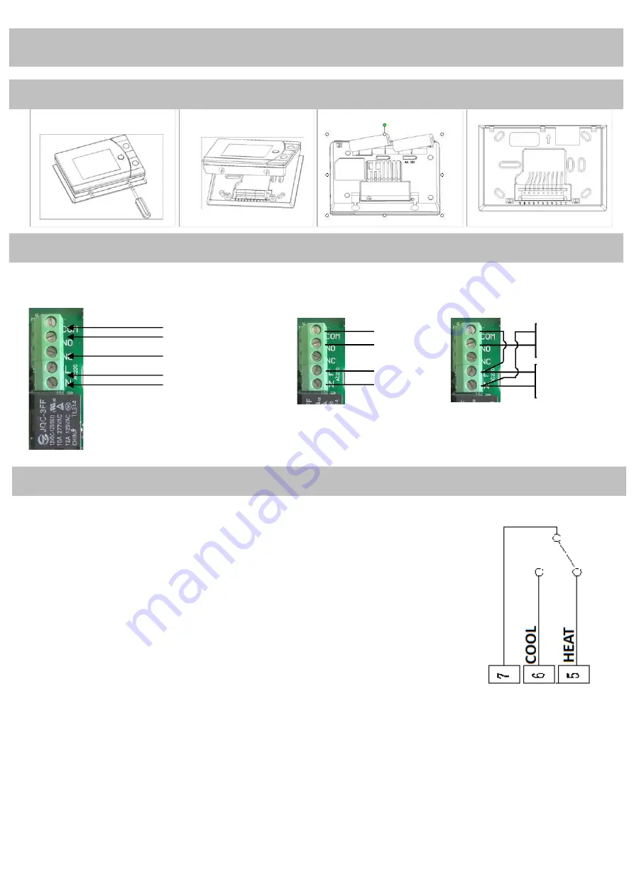
The receiver can be mounted directly on a wall or in a flush-mounted box. Remove the fascia panel first of all; there are two indentations on the bottom
side which can be pushed in using a screwdriver.
The receiver has a connecting terminal which has 5 connections.
The RF Optima Basic Plus has also a connection terminal for heating or cooling OR for automatically heating/cooling by a heatpump
3
RF-OPTIMA BASIC
PLUS THERMOSTAT
Inserting/replacing the thermostat batteries:
Assembling and connecting the receiver:
COM: Common contact
NO: Normally-open contact
NC: Normally-closed contact
L + N: Electrical connection
230VAC.
Connection data Heating
Electric heating
Electrical
connection
230VAC.
Electrical
connection
230VAC.
Electric heating
element
(230VAC/10A)
Thermostat-
connection
Boiler
Heat or cool mode, automatic heat or cool mode
;
The RF thermostat has on the backside 3 pins which is connecting a green or black terminal on the mounting plate
which can be used for heating or cooling mode. The default setting is heat, but when the terminal 7 and 6 are being
connected, the thermostat is set for cool mode. This connection can be made with a thin electric wire 0,25mm2
When the thermostat must be act automaticly, e.g by heatpump, make the wiring as below.
The main heat/cool installation must have a volt free output!
– Connect on terminal 7 the COMMON wire.
– Connect on terminal 6 the COOL wire.
– Connect on terminal 5 the HEAT wire.
When the heat/cool installation generate heat, contact 7 and 5 should be activated. When the heat/cool installation
generate cooling, contact 7 and 6 should be activated.
Minimum wire thickness for this cable is 0,75mm2

