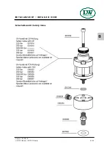
OPERATING INSTRUCTION FOR SAFETY VALVE
Page
2
In order to prevent manipulation of the set pressure, all safety valves are factory fitted with a seal.
A safety valve on which the seal has been removed, must be returned to the manufacturer for
repair / adjustment before further use.
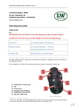
In addition, the safety valve has a venting device (hand wheel).
When rotated clockwise, the safety valve and the filter housing of the final stage are completely
vented.
During normal operation, the screw is unscrewed to the upper stop anticlockwise; an integrated
safety ring prevents the screw from being removed.
If a safety valve blows off, the system must be switched off immediately and the cause of the error,
investigated.
There are two possible reasons:
1. The safety valve is defective and blows off before the set pressure.
In this case the safety valve should be submitted immediately to the manufacturer for repair or
replaced with a new one.
2. The safety valve opens properly, the problem is on the system.
A constant blowing of the safety valve is not permitted, the sealing seat of the valve can be damaged.
The error on the system must be detected and repaired before further filling operations.
The safety valve may only be used if it is ensured that the maximum flowrate of the system does not
exceed the blow-off rate of the safety valve.
The safety valve may only be used with the approved media.
Repair work on compressors must only be performed by trained personnel.
Dismantling of the safety valve
Ensure that on the safety valve is no pressure.
Loosen and remove the two M8 fixing bolts with a 6 mm Allen key.
The safety valve can now be removed by turning and simultaneously pulling out of the socket.
Mounting
1. Clean the safety valve socket.
2. Oil the insert pin of the safety valve including the O-ring with 1 to 2 drops of oil.
3. Press the safety valve pin complete into the socket.
4. Fasten the safety valve with the two 8 mm allen screws into the socket
(Tightening torque: 10 Nm)
5. Screw the venting screw (hand wheel) anticlockwise to its upper limit.
6. Start the System (Compressor), check installation for leaks and proper function.
Summary of Contents for LW 170 D Nautic / AL
Page 14: ...Page A 12 A LW 170 E LW 170 D Nautic Version 15 10 2019 D E S C R I P T I O N Flow chart ...
Page 15: ...Page A 13 A LW 170 E LW 170 D Nautic Version 15 10 2019 S A F E T Y P R E C A U T I O N S ...
Page 22: ...Page A 20 A LW 170 E LW 170 D Nautic Version 15 10 2019 I N S TA L L AT I O N ...
Page 31: ...Page A 29 A LW 170 E LW 170 D Nautic Version 15 10 2019 O P E R AT I O N ...
Page 39: ...Page A 37 A LW 170 E LW 170 D Nautic Version 15 10 2019 R E M E D Y I N G FA U LT S ...
Page 86: ...Page A 84 A LW 170 E LW 170 D Nautic Version 15 10 2019 M A I N T E N A N C E R E C O R D S ...
Page 95: ...B ERSATZTEILLISTEN SPARE PARTS LISTS DETAILANSICHTEN DETAILED VIEWS ...

