Page A - 59
A
LW 170 E / LW 170 D Nautic
Version: 15.10.2019
Valve heads and valves
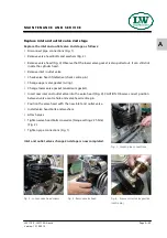
Inlet and outlet valves of the specific compressor stages are
located between valve head and cylinder. Inlet valves open
on piston downstroke; outlet valves open on upstroke or
compression stroke.
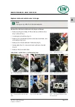
Valves are subject to normal wear and tear and have to be
replaced at specified intervals (depending on specific opera-
ting conditions). Dismount valve heads to change valves. In
1st stage there is an inlet valve and an outlet valve in use.
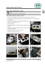
The valves of 2nd and 3rd stage are combined valves; inlet
and outlet valves are a single unit.
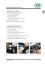
To change the inlet– and outlet valves it is necessary to remo-
ve the fan protection cover!
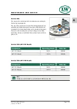
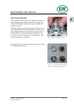
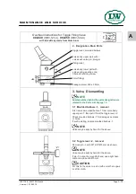
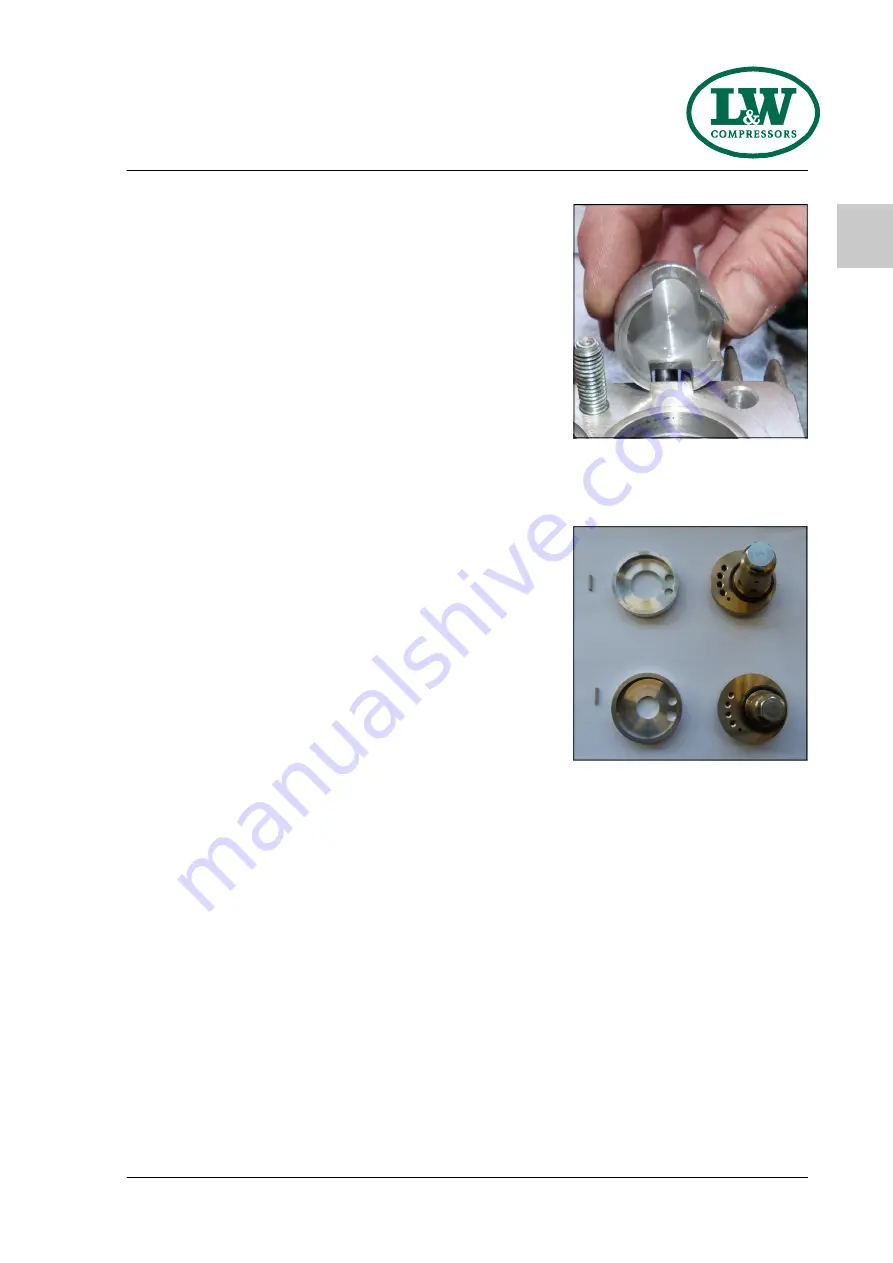
Fig. 2 - In – and outlet valve c/w gaskets
2nd stage (top) and 3rd stage (below)
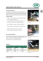
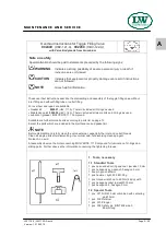
Fig. 1 - Outlet valve holder 1st. stage
M A I N T E N A N C E A N D S E R V I C E
Summary of Contents for LW 170 D Nautic / AL
Page 14: ...Page A 12 A LW 170 E LW 170 D Nautic Version 15 10 2019 D E S C R I P T I O N Flow chart ...
Page 15: ...Page A 13 A LW 170 E LW 170 D Nautic Version 15 10 2019 S A F E T Y P R E C A U T I O N S ...
Page 22: ...Page A 20 A LW 170 E LW 170 D Nautic Version 15 10 2019 I N S TA L L AT I O N ...
Page 31: ...Page A 29 A LW 170 E LW 170 D Nautic Version 15 10 2019 O P E R AT I O N ...
Page 39: ...Page A 37 A LW 170 E LW 170 D Nautic Version 15 10 2019 R E M E D Y I N G FA U LT S ...
Page 86: ...Page A 84 A LW 170 E LW 170 D Nautic Version 15 10 2019 M A I N T E N A N C E R E C O R D S ...
Page 95: ...B ERSATZTEILLISTEN SPARE PARTS LISTS DETAILANSICHTEN DETAILED VIEWS ...

