LX Navigation d.o.o. LX 7007 C May. 30th 2012
- 19 -
Note!
Every setting should be set twice once for vario mode and
once for SC mode.
2.3.2.8
TE comp.
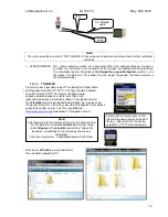
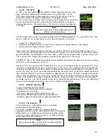
LX 7007 C has the capability to offer variometer total energy compensation in two
ways. Selection of compensation method is done after selection the % figure.
000% means total energy compensation when using a TE tube. When using this
solution the unit does not process compensation this depends entirely
on the TE tube and its installation. After an input of a percentage which is other than
zero
the special software routines will be activated and will provide an electronic
compensation process. The default value is 100% but this can be varied following
a test flight.
The TE compensation can be fine tuned during flight with the following procedure. It is essential that this is only
done in smooth air; it is not possible to tune the TE accurately when it is thermic.
•
Select 100 % and default TEF
•
Accelerate up to approximately 160 km/h (75 kts) and keep the speed stable for a few seconds
•
Gently reduce the speed to 80 km/h (45 kts)
Observe the vario indicator during the manoeuvre. At 160 km/h (75 Knots) the vario will indicate about –2 m/s
(-4kts). During the speed reduction the vario should move towards zero and should never exceed zero (slightly
positive indications are acceptable). If the vario shows a climb, then the compensation is too low, increase the
TE%; and vice versa. Repeat this procedure and make further adjustments if necessary.
The
TEF
(TE filter) is the compensation delay. Larger numbers will increase the delay and vice versa. During
the first test is recommended to use TEF 4.
Electronic TE is only effective when the pitot and static sources are co-located and the pneumatic lines to the
instrument are approximately the same length. The best sensor to use is the combined pitot/static Prandtl tube.
If problems are experienced with the electronic TE compensation, then the most likely cause is the glider's static
source. The static source can be checked by plumbing the pneumatic tubes for electronic compensation and
then setting the
TE:
to 0%. In still air, accelerate to approximately 160 km/h (75 Knots) and reduce the speed.
Observe the vario indicator. If the static source is good, then the vario should immediately start to move to show
a climb. If the needle initially shows increased sink and then moves to a climb, the static source of the glider is
unsuitable and there is no way to provide successful TE compensation electronically. The use of a dedicated
and accurate fin mounted pitot/static source such as a Prandtl tube might help.
2.3.2.9
Altitude
warning
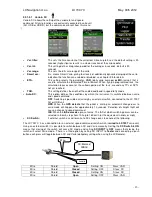
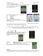
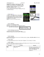
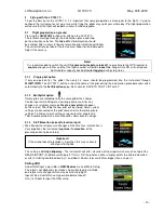
In case of an altitude limitation the pilot
is able to set the altitude value which is a top limit.
Three parameters are offered:
-Limit: means upper level which couldn’t be crossed
-Warn before: altitude margin where the warning will start
-Audio warn:
yes
will execute also an audio sound (didl, didl)
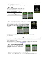
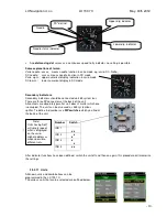
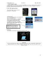
2.3.2.10 LCD Indicator
LCD indicator means vario indicator with it
’
s mechanical
needle and colour graphic display.
The system is capable to drive also secondary indicators.
Secondary indicators may be simple repeaters or may also indicate
different data sets, it all depends on the indicator number
setting.
Vario unit is always addressed as Number 1, secondary indicators
can be addressed from 1 up to four.
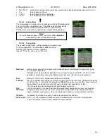
Note!
Electronic and pneumatic TE compensation requires
different connection of tubes.

