106
Installation Procedure, LXE Models 6723 Bridge & 6720 AP (non-RoHS)
NEMA Type 4 Enclosure Reference Guide
E-EQ-NEMARG-F
159128-0001 Rev. C
Page 8 of 11
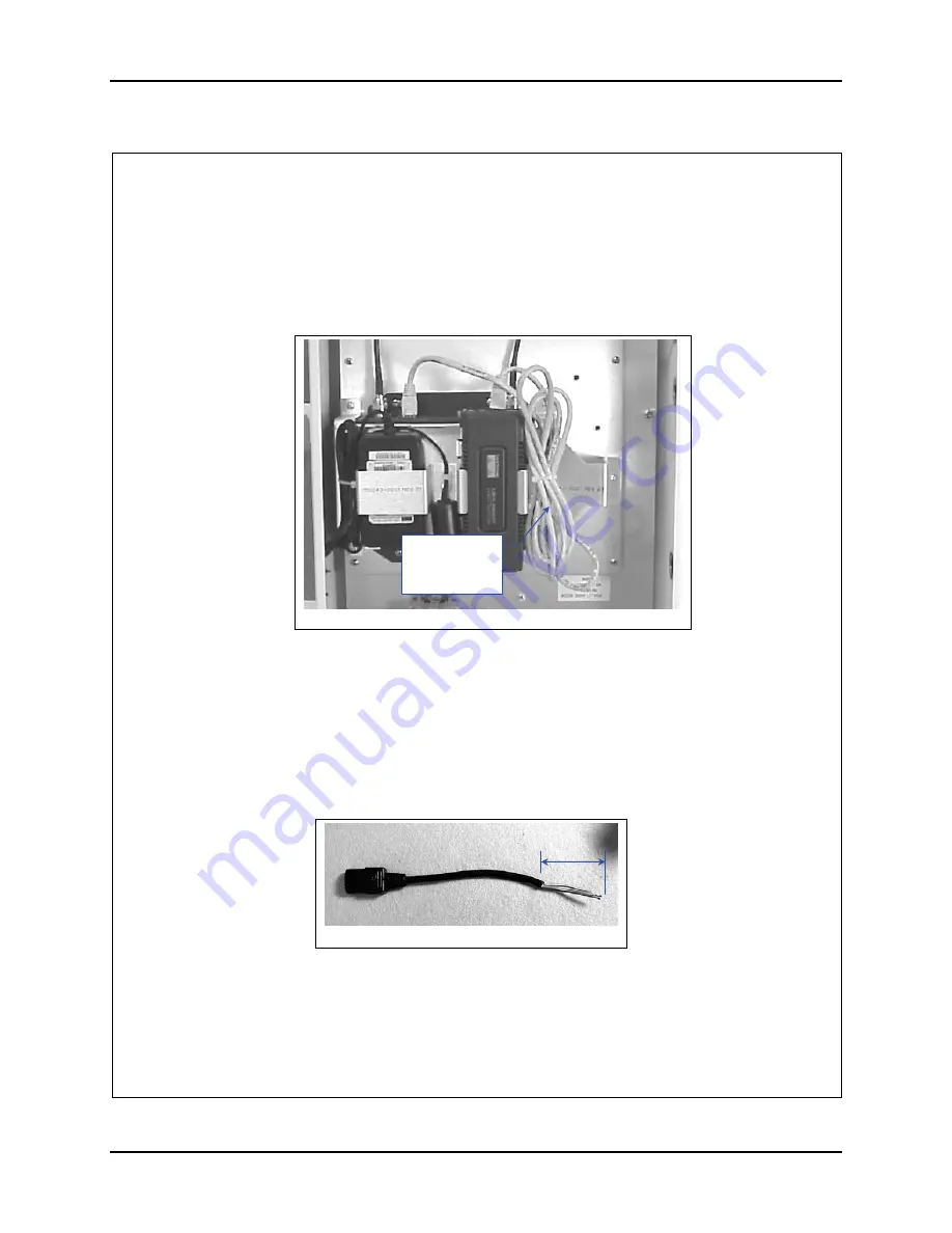
24. Connect the Ethernet Cable (supplied with the AP) to the Power Injector and
the AP. See figure 11.
25. Bundle it and secure it with a nylon cable tie on the
RIGHT
side of the Power
Injector. See figure 11.
26. Measure 21” from the universal plug end of the AC power cord (supplied with
the Cisco 350 Bridge) and cut. Discard the remainder of the cord.
27. Measure 10” from the universal plug end of the AC power cord (supplied with
the Cisco 350 AP) and cut. Discard the remainder of the cord.
28. Remove at least 2” inches of the outer covering from the cut end of each cord.
See figure 12.
29. Remove 0.4” (10 mm) of the insulation from each conductor.
30. Plug the short cord into the AP Power Brick.
31. Plug the long cord into the Bridge Power Brick.
Figure 12
2”
Figure 11
Ethernet cable
Supplied with
AP


