196
Installation Procedure, LXE Models 6723 Bridge & 6720 AP (RoHS)
NEMA Type 4 Enclosure Reference Guide
E-EQ-NEMARG-F
159128-0001-R Rev. A
Page 6 of 11
14. Place a nylon tie down over the screw holes of the brackets. See figure 6.
15. Secure the tie downs and the bracket with three (3) 6-32x 5/16” long screws.
16. Route the power cord from the Power Injector between the Power Brick and
the Power Injector and secure the ferrite with a nylon cable tie. See figure 7.
17. Route the power cord around the top of the Power Brick.
18. Bundle it and secure it with a nylon cable tie on the
LEFT
side of the Power
Brick. See figure 7.
19. Repeat steps 11-18 for the Bridge. Route the Crossover Cable under the
brackets.
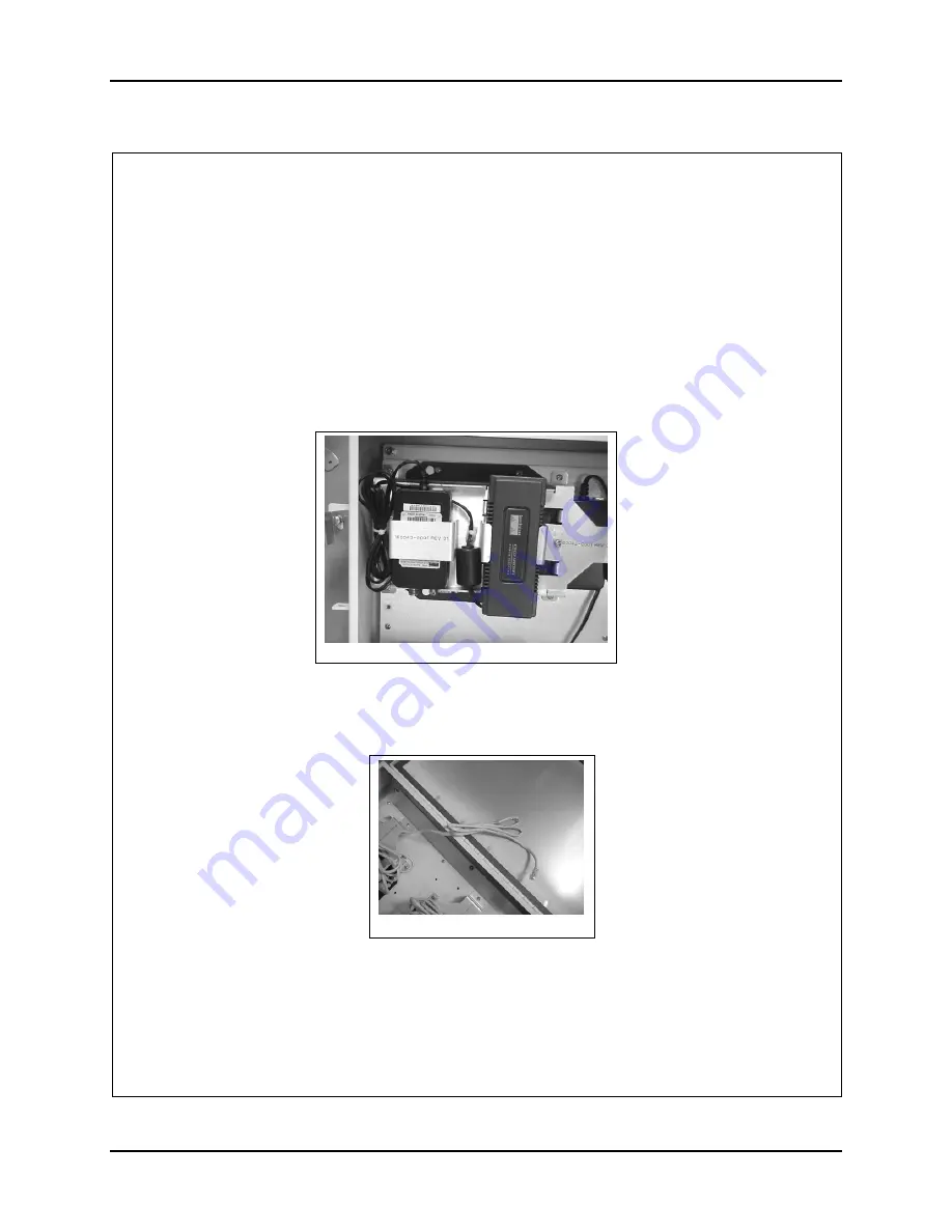
20. Bundle the cable and secure it with a nylon cable tie. See figure 8.
Figure 8
Figure 7


