background image

52 

Installation Procedure, LXE Models 6453 Bridge & 6540 AP (non-RoHS) 

NEMA Type 4 Enclosure Reference Guide 

E-EQ-NEMARG-F 

159086-0001 Rev. B 

Page 2 of 10  

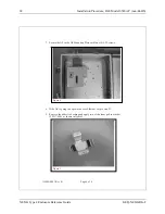
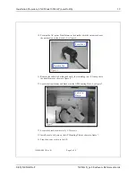
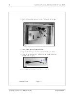
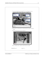
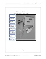
1. Remove the hardware Package from the enclosure.  

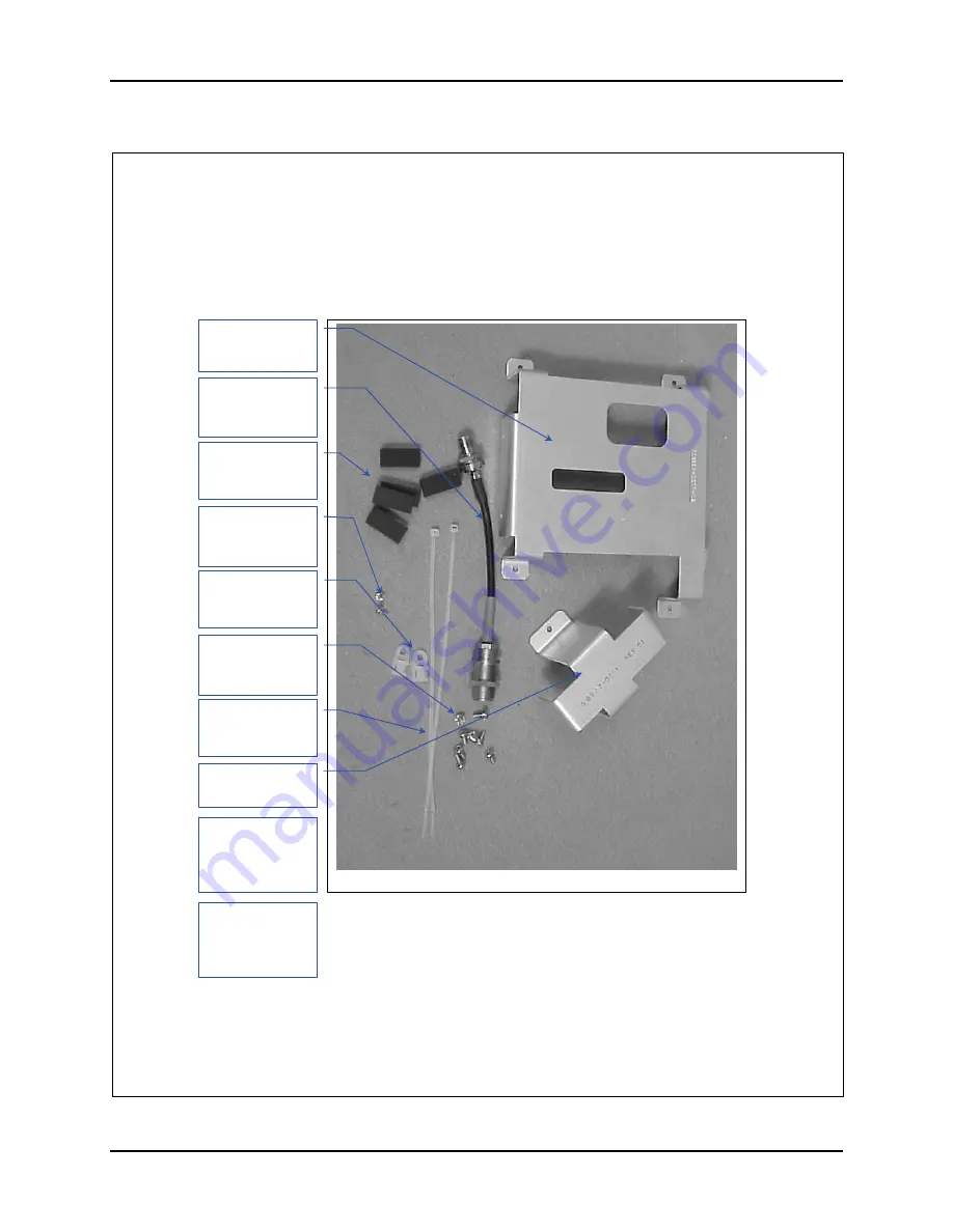
2. Remove contents and verify the quantities. See figure 1. 

Hardware Package 

Figure 1 

Antenna Cable 
 (158887-0001) 
Qty. 1 

Bracket, Qty. 2 
 (158934-0001)

 Nylon Tie Down 
(703006-0000)
Qty. 2 

#6-32 Screw, 
5/16”long. Qty 14 
(137646-0606) 

8” Nylon Tie 
(703028-0000)
Qty. 3 

Bracket, Qty. 2 
 (158937-0001) 

#4-40 Screw, 
1/4”long. Qty 4 
(137646-0404)

Pad, Foam 
(155154-0001)
Qty. 10 

Antenna Cable 
(159078-0001)
Qty 2 
Not Shown 

Crossover Cable 
(425042-0836)
Qty 1 
Not Shown 


Summary of Contents for Nema 4

Page 1: ...NEMA Type 4 Enclosure Reference Guide Copyright December 2006 by LXE Inc All Rights Reserved E EQ NEMARG F ...

Page 2: ... 4224 Trademarks LXE is a registered trademark of LXE Inc All other brand or product names are trademarks or registered trademarks of their respective companies or organizations When this manual is in PDF format Acrobat Reader Copyright 1987 2006 Adobe Systems Incorporated All rights reserved Adobe the Adobe logo Acrobat and the Acrobat logo are trademarks of Adobe Systems Incorporated applies Imp...

Page 3: ...tion Explanation Chapter 1 Introduction Updated accessories listing Appendix B I nstallation Procedure Sheets Renamed to Appendix B Installation Procedure Sheets non RoHS Revised section Introduction Appendix C Installation Procedure Sheets RoHS Added new appendix Note A complete revision history is included in Appendix A Technical Specifications ...

Page 4: ......

Page 5: ... to Use This Guide 10 Document Conventions 10 Getting Help 11 Accessories 11 CHAPTER 2 INSTALLATION 13 Step 1 Assemble Internal Components 13 Step 2 Mount NEMA Enclosure 15 Direct Wall Mount 15 Using a Mounting Board 15 Step 3 Route AC Power and Ethernet 16 Important Notes 18 Step 4 Complete Installation 19 Fuse Replacement 19 Completed Installation 20 APPENDIX A TECHNICAL SPECIFICATIONS 21 Physic...

Page 6: ...e 6730 AP non RoHS 83 Installation Procedure LXE Models 6723 Bridge 6720 AP non RoHS 99 Installation Procedure Lightning Suppression Accessories non RoHS 111 APPENDIX C INSTALLATION PROCEDURE SHEETS ROHS 117 Introduction 117 Installation Procedure LXE Model 6520 AP RoHS 119 Installation Procedure LXE Model 6540 AP RoHS 127 Installation Procedure LXE Model 6543 Bridge RoHS 135 Installation Procedur...

Page 7: ...e View 6 Figure 3 NEMA Enclosure Top View 7 Figure 4 NEMA Enclosure Bottom View 7 Figure 5 NEMA Enclosure Left Latch side View 8 Figure 6 NEMA Enclosure Right Hinge side View 9 Figure 7 Watertight Plugs 14 Figure 8 Mounting Template 15 Figure 9 Terminal Block Wiring Connections 17 Figure 10 Fuse Holder 19 Figure 11 NEMA Enclosure Typical Installation 20 ...

Page 8: ...iv Table of Contents NEMA Type 4 Enclosure Reference Guide E EQ NEMARG F ...

Page 9: ...d into harsh environments where dust or water may damage traditional mounted devices With the optional heater network coverage can be added in extreme temperature environments The NEMA enclosure protects wireless access points and bridges from rain snow ice hose spray dust and sand External Interfaces The Enclosure provides provisions for external connections through watertight entrances as detail...

Page 10: ...ollow the instruction in the Installation Kit to ensure a watertight seal is made Any unused antenna holes must be securely covered by the hole plugs included with the Enclosure Optional lightning protection is available for each of the four antenna connections The actual number of suppressors included with the Enclosure depends upon the configuration specified when ordering Please contact your LX...

Page 11: ...ities Note Optional lightning suppression for AC power is available on the Enclosure Enclosed Devices The Enclosure is designed to house Access Points and bridges LXE offers mounting kits for the following devices LXE 6730 Cisco Aironet 1200 802 11b Access Point LXE 6740 Cisco Aironet 1200 802 11g Access Point LXE 6723 Cisco Aironet 350 Wireless Bridge LXE 6720 Cisco Aironet 350 Access Point LXE 6...

Page 12: ...e of the enclosed device The heater is enabled when the ambient temperature is below 15º C 59º F Power is supplied to enclosed devices when the internal temperature is above 0º C 32º F Lightning Suppression The Enclosure has optional lightning protection Lightning protection is available for any combination of the following areas AC power Ethernet Up to four RF antenna connections Lightning protec...

Page 13: ...ounted on a wall 1 2 1 Clips and Screws 2 Latch for User Supplied Padlock Figure 1 NEMA Enclosure Front View Please note that the AC power and Ethernet connections are on the bottom of the unit when installed To preserve the NEMA Type 4 rating the Enclosure must be mounted with the AC power and Ethernet connectors on the bottom ...

Page 14: ...LE FOR INSTALLATION IN WET LOCATIONS E 205841 INDUSTRIAL CONTROL PANEL ENCLOSURE ISSUE NO XXXXXXX LISTED C US UL 1 Clips and Screws 6 Terminal Block Includes Fuse Holder 2 Latch for User Supplied Padlock 7 AC Power Inlet 3 AP Mounting Plate 8 Ethernet Cable Inlet 4 Thermostats Heated Enclosures only 9 Lid 5 Base Plate 10 Hinge Figure 2 NEMA Enclosure Inside View Note LXE installed internal wiring ...

Page 15: ...igure 3 NEMA Enclosure Top View Please note there are no connectors on the top of the Enclosure This view represents the bottom of the Enclosure as mounted on a wall 1 2 3 1 Clips and Screws 2 AC Connector 3 Ethernet Connector Figure 4 NEMA Enclosure Bottom View Please note the connectors for AC power and Ethernet cable are on the bottom of the Enclosure ...

Page 16: ... E EQ NEMARG F This view represents the left or latch side of the Enclosure as mounted on a wall 1 2 1 Clips and Screws 2 Latch for User Supplied Padlock Figure 5 NEMA Enclosure Left Latch side View Please note the provision for a user supplied padlock ...

Page 17: ...e right or hinge side of the Enclosure as mounted on a wall 1 2 1 Clips and Screws 2 Holes for External Antennas Figure 6 NEMA Enclosure Right Hinge side View Please note the front cover is not removable Note Any unused antenna holes must be securely sealed with provided plugs and hardware ...

Page 18: ...rocedure Sheets non RoHS provides copies of the instructions provided with AP bridge install kits and lightning suppression install kits for countries that do not require RoHS compliant items Appendix C Installation Procedure Sheets RoHS provides copies of the instructions provided with AP bridge install kits and lightning suppression install kits that require RoHS compliant items Document Convent...

Page 19: ... that meet the RoHS compliance standards Install Kit 6720 or 6723 Install Kit 6730 6740 Install Kit 6520 Install Kit 6540 Install Kit 6543 Install Kit 6540 6543 Install Kit 6720 6723 Install Kit 6730 6740 6723 Note Install kits include brackets screws cables instruction sheet etc necessary to install the enclosed device in the Enclosure These kits DO NOT include the AP or Bridge Please contact you...

Page 20: ...12 Accessories NEMA Type 4 Enclosure Reference Guide E EQ NEMARG F ...

Page 21: ... NEMA enclosure using the brackets from the install kit A copy of the installation sheet is provided in Appendix B Installation Procedure Sheets non RoHS or Appendix C Installation Procedure Sheets RoHS Following the instruction sheet route any necessary internal AC wires from the terminal block to the enclosed device s Following the instruction sheet route any necessary internal Ethernet cables F...

Page 22: ...Q NEMARG F When all internal components are installed ensure that any unused connection holes are securely plugged Figure 7 Watertight Plugs Note Lid enclosed components and other internal details omitted for clarity The NEMA enclosure is ready to be mounted in the desired location ...

Page 23: ...to allow for easy installation Please refer to the template above for mounting dimensions Caution If the enclosure cannot be attached to wall studs or other surfaces capable of supporting up to 20 lbs 9 kg the NEMA enclosure must be attached to a mounting board The mounting board must be securely attached to the wall Using a Mounting Board An appropriate mounting board should be used LXE recommend...

Page 24: ...ion If this option was not ordered LXE recommends either purchasing the lightning suppression kit or adding an external provision for surge protection In addition it may be desirable to add a Uninterruptible Power Supply UPS to the circuit Caution Risk of electric shock Disconnect AC electrical branch circuit or DC power supply before proceeding Use OSHA LOCK OUT TAG OUT procedures for safe and pr...

Page 25: ...te the line wire to the terminal marked L Route the neutral wire to the terminal marked N Route the ground green or green with yellow stripe wire to the middle terminal identified by the ground symbol 4 Run an Ethernet cable if desired to the Enclosure and use a NEMA rated connector to rout the Ethernet cable through the opening located on the bottom right of the enclosure Figure 9 Terminal Block ...

Page 26: ...osed devices The maximum supply wire size suitable for connection to the field wiring terminal strip is 12 AWG stranded or solid copper conductors only The maximum branch circuit overcurrent protective device OCPD acceptable for use is 20A ampere for 120V supply circuits and 10A for 240V supply circuits The enclosed devices are only for connection to electrical supply circuits using a grounded neu...

Page 27: ...tents of the Enclosure Once the box is secured return power to the electrical circuit Caution If the Enclosure must be reopened for any reason the AC power MUST BE turned off before opening the enclosure Fuse Replacement Both the 120V and 240V units use a 250V 5A Fast Blow fuse Caution For continued protection against risk of fire replace only with the same type and rating of fuse The fuse holder ...

Page 28: ...20 Completed Installation NEMA Type 4 Enclosure Reference Guide E EQ NEMARG F Completed Installation Figure 11 NEMA Enclosure Typical Installation Note AC wiring and Ethernet cabling not shown ...

Page 29: ...93 cm All dimensions are measured with no external antennas installed Environmental Specifications Feature Specification Comments 0 ºC to 50 ºC 32 ºF to 122 ºF 1 Base unit Operating Temperature 30 ºC to 50 ºC 22 ºF to 122 ºF 1 Base unit with heater Storage Temperature 40 ºC to 60 ºC 40 ºF to 140 ºF Water Sand and Dust Type 4 rating Lightning Protection Waveform of 8 μs rise time by 20 μs fall time...

Page 30: ... 7 50 W LXE 6730 Cisco AP 1200 802 11b 7 20 W 8 50W LXE 6740 Cisco AP 1200 802 11g 7 20 W 8 50W AC Heater 261 0 W 291 0 W Notes Enclosed devices are assumed to be rated for 70º C 158º F If enclosed devices are not rated for this temperature the maximum temperature for the Enclosure must be adjusted accordingly The power requirement for enclosed Access Points and Bridges is 120 or 240V AC 1 0 Amp M...

Page 31: ...ection Explanation Appendix B Installation Procedure Sheets Replaced the Revision A of the following Installation Procedure Sheet with Revision B 159083 0001 Revision D August 2005 Section Explanation Front cover Updated with 2005 LXE logo Updated notices and copyrights Entire Manual Updated all images with LXE logo to reflect the 2005 LXE logo Chapter 1 Introduction Added 6740 to Enclosed Devices...

Page 32: ... archive section of the LXE ServicePass website The archive copy of this manual includes these installation sheets Revision E April 2006 Section Explanation Appendix A Technical Specifications Added Revision History Appendix B Installation Procedure Sheets Updated Introduction section Replaced the Revision B of the following Installation Procedure Sheet with Revision C 159088 0001 Revision F Augus...

Page 33: ...nstallation Kit Instructions Please refer to 159083 0001 Installation Procedure LXE Model 6520 AP Orinoco AP1000 NEMA 4 Enclosure Rev B 6540 Installation Kit Instructions Please refer to 159084 0001 Installation Procedure LXE Model 6540 AP Proxim AP600 NEMA 4 Enclosure Rev B 6543 Installation Kit Instructions Please refer to 159085 0001 Installation Procedure LXE Model 6543 Bridge Proxim MP11 NEMA...

Page 34: ...E Model 6740 AP with an LXE Model 6723 Bridge 6720 and 6723 Installation Kit Instructions Please refer to 159128 0001 Installation Procedure LXE Model 6723 Bridge Cisco 350 Bridge LXE Model 6720 AP Cisco 350AP NEMA 4 Enclosure Rev C Lightning Suppression Kit Please refer to 159333 0001 Installation Procedure For Lightning Suppression Accessories Rev B for installation of the following RF ANT Surge...

Page 35: ... F NEMA Type 4 Enclosure Reference Guide Installation Procedure LXE Model 6520 AP non RoHS 159083 0001 Rev B Page 1 of 7 159083 0001 Rev B INSTALLATION PROCEDURE LXE Model 6520 AP Orinoco AP 1000 NEMA 4 ENCLOSURE ...

Page 36: ...1 Rev B Page 2 of 7 1 Remove the hardware package from the enclosure 2 Remove contents and verify the quantities See figure 1 Hardware Package Figure 1 Antenna Cable 155724 0001 Qty 3 Nylon Tie Down 703006 0000 Qty 1 8 Nylon Tie 703028 0000 Qty 2 8 32 Screw 1 4 long Qty 4 137646 0804 Antenna Cable 155723 0001 Qty 1 ...

Page 37: ... 159083 0001 Rev B Page 3 of 7 3 Remove the locating tab from the AP Mounting Plate See figures 2 and 3 4 Break the tab off by bending back and forth with a pair of pliers Discard the tab 5 Locate the Orinoco AP 1000 mounting bracket on the AP Mounting Plate see figure 4 Figure 3 Figure 2 Remove this Tab ...

Page 38: ...e Guide E EQ NEMARG F 159083 0001 Rev B Page 4 of 7 6 Secure the AP Mounting Bracket to the AP Mounting Plate with three 3 8 32 screws See figure 4 7 Plug the power cord supplied with the AP into the power brick 8 Insert the power brick into the bracket See figure 5 Figure 4 Figure 5 ...

Page 39: ...ale end 11 Remove at least 2 inches of the outer covering from the cut end of each cord See figure 6 12 Remove 0 4 10 mm of the insulation from each conductor 13 Insert the conductors of the cord into the terminal block on the LEFT side Neutral marked blue Live unmarked Ground to Ground marked green See figure 7 Figure 7 Right side connection shown Neutral Marked Blue Live Unmarked Ground Marked G...

Page 40: ...wer cord to the tie down with the 8 nylon cable tie See figure 8a Pull it tight and trim 16 Remove the two 2 plugs closest to the top located on the hinge side of the enclosure 17 Insert the long antenna cable 155723 0001 in the FIRST opening from the top of the enclosure See figure 9 Secure it with the lock washer and nut 18 Route the cable to the radio closest to the top of the AP Connect it to ...

Page 41: ...20 Route the cable to the radio closest to the top of the AP Connect it to the radio See figure 9 21 If more than one radio is installed remove the two 2 remaining plugs and insert an antenna cable 155724 0001 in the THIRD and FOURTH openings from the top of the enclosure See figure 10 Secure it with the lock washer and nut 22 Route the cables to the other radio of the AP Connect it to the radio S...

Page 42: ...34 Installation Procedure LXE Model 6520 AP non RoHS NEMA Type 4 Enclosure Reference Guide E EQ NEMARG F ...

Page 43: ...RG F NEMA Type 4 Enclosure Reference Guide Installation Procedure LXE Model 6540 AP non RoHS 159084 0001 Rev B Page 1 of 8 159084 0001 Rev B INSTALLATION PROCEDURE LXE Model 6540 AP Proxim AP600 NEMA 4 ENCLOSURE ...

Page 44: ...ackage from the enclosure 2 Remove contents and verify the quantities See figure 1 Hardware Package Figure 1 Antenna Cable 159078 0001 Qty 2 Bracket Qty 1 1589348 0001 Nylon Tie Down 703006 0000 Qty 2 6 32 Screw 5 16 long Qty 8 137646 0606 8 Nylon Tie 703028 0000 Qty 2 Bracket Qty 1 158937 0001 4 40 Screw 1 4 long Qty 2 137646 0404 Pad Foam 155154 0001 Qty 5 ...

Page 45: ...8 3 Prep the Bracket to accept the AP Remove the adhesive backing and apply a foam pad 155154 0001 to bracket 158941 0001 as shown in figure 2 4 Insert the AP top first into the bracket 5 Secure the AP with the two 2 4 40 screws See figure 3 6 Locate the AP secured in the bracket on the AP Mounting plate Figure 2 Figure 3 4 40 Screws ...

Page 46: ... EQ NEMARG F 159084 0001 Rev B Page 4 of 8 7 Secure the AP to the AP Mounting Plate with four 4 6 32 screws 8 If the AP is going to be powered over Ethernet skip to step 22 9 Remove the adhesive backing and apply two of the foam pad to bracket 158937 0001 as shown in figure 5 Figure 4 Figure 5 ...

Page 47: ...ab on the bracket See figure 6 11 Remove the adhesive backing and apply the remaining two 2 foam pads to the transformer as shown in figure 6 12 Locate the transformer and bracket on the AP Mounting Plate See figure 7 13 Secure the bracket with two 2 6 32 screws 14 Install a cable tie down on the AP Mounting Plate as shown in figure 7 15 Plug the power cord in to the AP Figure 6 Notched Tab Foam P...

Page 48: ...and secure it with an 8 nylon cable tie See figure 8 17 Obtain a female power cord Supplied Locally 18 Plug the cord into the power transformer and route it to the terminal block 19 Cut the cord and remove at least 2 inches of the outer covering from the cut end of the cord See figure 9 20 Remove 0 4 10 mm of the insulation from each conductor Figure 9 2 Figure 8 ...

Page 49: ...erminal block Neutral marked blue Live unmarked Ground to Ground marked green See figure 10 22 Remove the two 2 plugs located on the hinge side of the enclosure closest to the top 23 Route the antenna cables as shown in figure 10 24 Insert the antenna cable connectors in the holes and secure them Figure 10 Neutral Marked Blue Live Unmarked Ground Marked Green Figure 11 ...

Page 50: ... F 159084 0001 Rev B Page 8 of 8 25 Plug the antenna cables into the AP 26 Install a cable tie down on the AP mounting plate as shown in figure 12 27 Secure the power cord to the tie down with an 8 nylon cable tie Pull it tight and trim 28 Connect Power and Data cables per installation manual Figure 12 ...

Page 51: ... NEMA Type 4 Enclosure Reference Guide Installation Procedure LXE Model 6543 Bridge non RoHS 159085 0001 Rev B Page 1 of 8 159085 0001 Rev B INSTALLATION PROCEDURE LXE Model 6543 Bridge Proxim MP11 NEMA 4 ENCLOSURE ...

Page 52: ... hardware Package from the enclosure 2 Remove contents and verify the quantities See figure 1 Figure 1 Antenna Cable 158887 0001 Qty 1 Bracket Qty 1 158934 0001 Nylon Tie Down 703006 0000 Qty 3 6 32 Screw 5 16 long Qty 9 137646 0606 8 Nylon Tie 703028 0000 Qty 3 Bracket Qty 1 158937 0001 4 40 Screw 1 4 long Qty 2 137646 0404 Pad Foam 155154 0001 Qty 5 ...

Page 53: ...3 Prep the Bracket to accept the AP Remove the adhesive backing and apply a foam pad 155154 0001 to bracket 158941 0001 as shown in figure 2 4 Insert the Bridge top first into the bracket 5 Secure the Bridge with two 2 4 40 screws See figure 3 6 Locate the Bridge secured in the bracket on the AP Mounting plate Figure 2 Figure 3 4 40 Screws ...

Page 54: ...pe 4 Enclosure Reference Guide E EQ NEMARG F 159085 0001 Rev B Page 4 of 8 7 Secure the Bridge to the AP Mounting Plate with four 4 6 32 screws 8 Remove the adhesive backing and apply two of the foam pads to bracket 158937 0001 as shown in figure 5 Figure 4 Figure 5 ...

Page 55: ...ab on the bracket See figure 6 10 Remove the adhesive backing and apply the remaining two 2 foam pads to the transformer as shown in figure 6 11 Locate the transformer and bracket on the AP Mounting Plate See figure 7 12 Secure the bracket with two 2 6 32 screws 13 Install a cable tie down on the AP Mounting Plate as shown in figure 7 14 Plug the power cord in to the Bridge Figure 6 Notched Tab Fo...

Page 56: ...p and secure it with an 8 nylon cable tie See figure 8 16 Obtain a female power cord Supplied Locally 17 Plug the cord into the power transformer and route it to the terminal block 18 Cut the cord and remove at least 2 inches of the outer covering from the cut end of the cord See figure 9 19 Remove 0 4 10 mm of the insulation from each conductor Figure 9 2 Figure 8 ...

Page 57: ...block Neutral marked blue Live unmarked Ground to Ground marked green See figure 10 21 Remove the plug located on the hinge side of the enclosure closest to the top 22 Install a cable tie down on the AP Mounting Plate as shown in figure 7 23 Insert the antenna cable into the hole and secure it Figure 10 Neutral Marked Blue Live Unmarked Ground Marked Green Figure 11 Cable Tie Down ...

Page 58: ...alled 25 Route the antenna cables as shown in figure 10 26 Secure the Antenna cables with an 8 nylon cable tie at the junction of the two cables Pull the cable tie tight and trim 27 Install a cable tie down on the AP mounting plate as shown in figure 13 28 Secure the power cord to the tie down with an 8 nylon cable tie Pull it tight and trim 29 Connect Power cable per installation manual Figure 12...

Page 59: ...re Reference Guide Installation Procedure LXE Models 6453 Bridge 6540 AP non RoHS 159086 0001 Rev B Page 1 of 10 159086 0001 Rev B INSTALLATION PROCEDURE LXE Model 6543 Bridge Proxim MP11 LXE Model 6540 AP Proxim AP600 NEMA 4 ENCLOSURE ...

Page 60: ...ntents and verify the quantities See figure 1 Hardware Package Figure 1 Antenna Cable 158887 0001 Qty 1 Bracket Qty 2 158934 0001 Nylon Tie Down 703006 0000 Qty 2 6 32 Screw 5 16 long Qty 14 137646 0606 8 Nylon Tie 703028 0000 Qty 3 Bracket Qty 2 158937 0001 4 40 Screw 1 4 long Qty 4 137646 0404 Pad Foam 155154 0001 Qty 10 Antenna Cable 159078 0001 Qty 2 Not Shown Crossover Cable 425042 0836 Qty 1...

Page 61: ...ccept the AP and the Bridge Remove the adhesive backing and apply a foam pad 155154 0001 to each bracket 158941 0001 as shown in figure 2 4 Insert the Bridge top first into the bracket Repeat for the AP 5 Secure the Bridge with two 2 4 40 screws See figure 3 Repeat for The AP 6 Locate the Bridge secured in the bracket on the AP Mounting plate Figure 2 Figure 3 4 40 Screws ...

Page 62: ... NEMA Type 4 Enclosure Reference Guide E EQ NEMARG F 159086 0001 Rev B Page 4 of 10 7 Secure the Bridge to the AP Mounting Plate with four 4 6 32 screws 8 Locate the AP secured in the bracket on the AP Mounting plate below the Bridge See figure 4a Figure 4 Figure 4a ...

Page 63: ...ce Guide 159086 0001 Rev B Page 5 of 10 9 Secure the Bridge to the AP Mounting Plate with four 4 6 32 screws 10 Install a cable tie down on the AP Mounting Plate as shown in figure 5 11 Remove the adhesive backing and apply two of the foam pads to each bracket 158937 0001 as shown in figure 6 Figure 6 Figure 5 ...

Page 64: ... 12 Position the AC power Transformer in the bracket with the output cord near the notched tab on the bracket See figure 7 13 Remove the adhesive backing and apply two 2 foam pads to each transformer as shown in figure 7 14 Locate the transformers in the bracket on the AP Mounting Plate See figure 8 Figure 7 Notched Tab Foam Pads Figure 8 Cable Tie ...

Page 65: ...Bridge 17 Plug the power cord from the lower transformer into the AP 18 Bundle the loose cords up and secure them with an 8 nylon cable tie See figure 8 19 Remove the plug located on the hinge side of the enclosure closest to the top 20 Install a cable tie down on the AP Mounting Plate as shown in figure 9 21 Insert the antenna cable 158887 0001 into the hole and secure it 22 Connect the Bridge an...

Page 66: ...te the antenna cables as shown in figure 10 24 Secure the Antenna cables with an 8 nylon cable tie at the junction of the two cables See figure 10 Pull the cable tie tight and trim 25 Remove the two 2 plugs located on the hinge side of the enclosure closest to the bottom 26 Route the antenna cables as shown in figure 11 Figure 11 Figure 10 Cable Tie here ...

Page 67: ...he Crossover cable between the AP and the Bridge 30 Secure the crossover cable and the AP antenna cables to the AP bracket See figure 12 Loop the cable tie between the bracket and the AP Pull it tight and trim 31 Obtain two 2 female power cords Supplied Locally 32 Plug a cord into each power transformer and route it to the terminal block 33 Cut the cords and remove at least 2 inches of the outer c...

Page 68: ...0001 Rev B Page 10 of 10 34 Remove 0 4 10 mm of the insulation from each conductor 35 Insert the conductors into the terminal block Neutral marked blue Live unmarked Ground to Ground marked green See figure 14 36 Connect Power per installation manual Figure 14 Neutral Marked Blue Live Unmarked Ground Marked Green Figure 13 2 ...

Page 69: ...RG F NEMA Type 4 Enclosure Reference Guide Installation Procedure LXE Model 6720 AP non RoHS 159087 0001 Rev C Page 1 of 8 159087 0001 Rev C INSTALLATION PROCEDURE LXE Model 6720 AP CISCO 350AP NEMA 4 ENCLOSURE ...

Page 70: ...he enclosure 2 Remove contents and verify the quantities See figure 1 Hardware Package Figure 1 Antenna Cable 158877 0001 Qty 2 Bracket Qty 1 160042 0001 Nylon Tie Down 703006 0000 Qty 3 6 32 Screw 5 16 long Qty 8 137646 0606 8 Nylon Tie 703028 0000 Qty 3 Bracket Qty 1 160046 0001 8 32 Screw 1 4 long Qty 4 137646 0804 Pad Foam 155154 0001 Qty 3 Bracket Qty 1 160043 0001 ...

Page 71: ...nclosure Reference Guide 159087 0001 Rev C Page 3 of 8 3 Locate the AP on the AP Mounting Plate See figure 2 4 Secure the AP to the AP Mounting Plate with four 4 8 32 screws See figure 2 5 If the AP is going to be powered over Ethernet skip to step 23 Figure 2 8 32 Screw long Qty 4 ...

Page 72: ...emove the adhesive backing and apply the three 3 foam pads to the bracket as shown in figure 3 7 Position bracket 160042 0001 over the AP See figure 4 8 Secure the bracket with five 5 6 32 screws 5 16 long 9 Plug the output power cord from the Power Brick into the Power Injector Route cable as shown in figure 5 Figure 3 Foam pads Figure 4 ...

Page 73: ... the AC input pointing towards the bottom of the box See figure 6 11 Position the Power Injector over the Foam Pad on bracket 160042 0001 up against the locating tabs with the RJ45 jacks pointed towards the top of the box See Figure 6 12 Place brackets 160043 0001 and 160046 0001 over the Power Brick and Injector See figure 6 Figure 6 Network RJ45 Conn AC power connector Cable Tie Down Installed H...

Page 74: ... 5 16 long screws 15 Route the power cord from the Power Injector between the Power Brick and the Power Injector and secure the ferrite with a nylon cable tie See Figure 7 16 Route the power cord around the top of the Power Brick 17 Bundle it and secure it with a nylon cable tie on the LEFT side of the Power Brick See figure 7 18 Connect the Ethernet Cable supplied with the AP to the Power Injecto...

Page 75: ...lied with the AP and cut Discard the remainder of the cord 21 Remove at least 2 inches of the outer covering from the cut end of the cord See figure 9 22 Remove 0 4 10 mm of the insulation from each conductor 23 Insert the conductors into the terminal block Neutral marked blue Live unmarked Ground to Ground marked green See figure 10 24 Plug the other end of the cable into the power brick 25 Conne...

Page 76: ... Reference Guide E EQ NEMARG F 159087 0001 Rev C Page 8 of 8 26 Remove the two 2 plugs located on the hinge side of the enclosure closest to the top 27 Route the Antenna Cables as shown in figure 11 28 Insert the Antenna Cable connectors in the holes and secure them Figure 11 ...

Page 77: ...G F NEMA Type 4 Enclosure Reference Guide Installation Procedure LXE Model 6730 AP non RoHS 159088 0001 Rev C Page 1 of 14 159088 0001 Rev C INSTALLATION PROCEDURE LXE Model 6730 AP CISCO 1200AP NEMA 4 ENCLOSURE ...

Page 78: ...move the hardware Package from the enclosure 2 Remove contents and verify the quantities See figure 1 Hardware Package Figure 1 Antenna Cable 158887 0001 Qty 2 Bracket 160042 0001 Qty 1 Nylon Tie Down 703006 0000 Qty 3 6 32 Screw 5 16 long Qty 10 137646 0605 8 Nylon Tie 703028 0000 Qty 4 Bracket 160043 0001 Qty 1 Pad Foam 155154 0001 Qty 3 ...

Page 79: ...on RoHS 71 E EQ NEMARG F NEMA Type 4 Enclosure Reference Guide 159088 0001 Rev C Page 3 of 14 3 Install the AP Mounting Bracket Supplied with the AP See figure 2 4 Secure the plate with 4 screws See figure 2 Figure 2 6 32 Screw 5 16 long Qty 4 ...

Page 80: ...wer right screw holding the mounting plate to the base plate See figure 3 6 Install one of the cable tie downs and secure it with the screw you removed earlier 7 Install the next cable tie near the AP bracket See figure 4 Secure it with a 6 32 screw Figure 3 Mounting Plate Base Plate Cable Tie Down Installed Here Figure 4 Cable Tie Down Installed Here ...

Page 81: ...LXE Model 6730 AP non RoHS 73 E EQ NEMARG F NEMA Type 4 Enclosure Reference Guide 159088 0001 Rev C Page 5 of 14 8 Determine which Model Power Brick Came with the AP See figure 5 9 For Model ADP 18PB skip to step 16 Figure 5 ...

Page 82: ... F 159088 0001 Rev C Page 6 of 14 10 Install two 2 of the Foam Pads on the mounting plate See figure 6 11 Remove the screw from the upper left corner of the Mounting Plate See figure 6 12 Apply the remaining Foam Pad to the top of the Power brick as shown in figure 7 Figure 7 Figure 6 Remove this screw ...

Page 83: ... of the foam pads placed on mounting plate earlier with the AC power connector pointed towards the bottom of the enclosure See figure 8 14 Position bracket 160042 0001 over the AP Power Brick See figure 8 15 Place a cable tie down over the screw hole on the right end of the bracket and secure it with a 6 32 screw See figure 8 Skip to step 25 Figure 8 Cable Tie down here ...

Page 84: ...er area of the enclosure See figure 9 19 Secure the bracket with four 4 6 32 x 5 16 long screws and the one that was removed form the Mounting Plate earlier 20 Remove the adhesive backing and apply two 2 of the Foam Pads to Bracket 160042 0001 as shown in figure 9 Discard the remaining Foam Pad 21 Position the AC Power Brick over the Foam Pads with the AC input pointing towards the bottom of the b...

Page 85: ...e 4 Enclosure Reference Guide 159088 0001 Rev C Page 9 of 14 23 Place a nylon tie down over the screw hole to the right of the power brick See figure 11 24 Secure the bracket and tie down with two 2 6 32 x 5 16 screws Figure 11 AC power connector Cable Tie Down Installed Here ...

Page 86: ...14 25 Place the AP on top of the AP Mounting bracket See figure 12 26 Align the AP up with the slots in the AP mounting bracket and slide it to the left to engage the pins 27 Secure the AP with an 8 cable tie See figure 13 Slide the tie through the slot located on the left side of the AP and pull it tight and trim Figure 12 Figure 13 ...

Page 87: ...ype 4 Enclosure Reference Guide 159088 0001 Rev C Page 11 of 14 28 Plug the power brick output cord into the AP See figure 14 29 Secure the ferrite to the tie down with one of the 8 nylon cable ties See figure 15 Trim the nylon tie after pulling it tight Figure 15 Figure 14 ...

Page 88: ... 16 31 Trim the nylon tie after pulling it tight 32 Obtain the power cord supplied with the AP 33 Measure 21 from the universal plug end of the AC power cord supplied with the AP and cut Discard the remainder of the cord 34 Remove at least 2 inches of the outer covering from the cut end of the cord See figure 17 35 Remove 0 4 10 mm of the insulation from each conductor 36 Plug the power cord into ...

Page 89: ...ower cord to the terminal block located in the lower left corner of the enclosure See figure 18 38 Secure the cord with an 8 Nylon tie to the tie down in the lower right corner of the mounting plate See figure 18 39 For power brick Model ADP 18PB route the power cord to the terminal block located in the lower left corner of the enclosure See figure 19 Figure 19 Figure 18 Tie down here ...

Page 90: ...d blue Black to Live unmarked Ground to Ground marked green See figure 20 41 Remove the two 2 lower plugs opposite the AP from the side of the enclosure 42 Install the antenna cables in the holes and tighten 43 Route the cables to the AP and connect them to the AP See figure 21 44 Connect Power and Data cables per installation manual Figure 20 Neutral Marked Blue Live Unmarked Ground Marked Green ...

Page 91: ...Reference Guide Installation Procedure LXE Models 6723 Bridge 6730 AP non RoHS 159089 0001 Rev C Page 1 of 15 159089 0001 Rev C INSTALLATION PROCEDURE LXE Model 6723 Bridge Cisco 350 Bridge LXE Model 6730 AP Cisco 1200 AP NEMA 4 ENCLOSURE ...

Page 92: ... the enclosure 2 Remove contents and verify the quantities See figure 1 Figure 1 Antenna Cable 158877 0001 Qty 4 Bracket Qty 1 160042 0001 Nylon Tie Down 703006 0000 Qty 6 6 32 Screw 5 16 lg Qty 14 137646 0606 8 Nylon Tie 703028 0000 Qty 6 Bracket Qty 1 160043 0001 8 32 Screw 1 4 long Qty 4 137646 0804 Pad Foam 155154 0001 Qty 6 Crossover cable 425042 0836 Bracket Qty 1 160046 0001 ...

Page 93: ...30 Mounting Bracket Cisco 1200 supplied with the AP on the AP Mounting Plate See figure 2 4 Secure the AP Mounting Bracket to the AP Mounting Plate with four 4 6 32 screws See figure 2 5 Locate the 6723 Bridge Cisco 350 on the AP Mounting Plate above the AP bracket with the antenna connectors towards the bottom See figure 3 Figure 2 Figure 3 8 32 Screw long Qty 4 ...

Page 94: ...erence Guide E EQ NEMARG F 159089 0001 Rev C Page 4 of 15 6 Secure the Bridge in place with four 4 8 32 screws 7 Apply two 2 foam pads 155145 0001 to the AP Mounting Plate as shown in figure 4 8 Apply a single foam pad to the AP Power Brick See figure 5 Figure 4 Foam Pads 155154 0001 Figure 5 ...

Page 95: ... top of the two foam pads between the bent up tabs with the AC power connector pointed towards the bottom of the enclosure See figure 6 10 Position bracket 160042 0001 over the Bridge and the AP Power Brick See figure 7 11 Place a cable tie down over the screw hole on the right end of the bracket and secure it with a 6 32 screw See figure 7 Figure 6 Figure 7 Cable Tie down here ...

Page 96: ...ews 5 16 long 13 Install a cable tie down in the AP Mounting Plate near the AP Bracket and secure it with a 6 32 screw See figure 8 14 Place the AP on top of the AP Mounting Bracket See figure 9 15 Align the AP up with the slots in the AP Mounting Bracket and slide it to the left to engage the pins 16 Route the power connector to the AP and plug it into the AP See figure 9 Figure 8 Figure 9 ...

Page 97: ...17 Secure the Ferrite on the power cord to the AP Mounting Plate with an 8 nylon cable tie 18 Bundle the power cord up and cable tie it to the tie down near the Power Brick See figure 10 19 Secure the AP with an 8 cable tie See figure 11 Slide the tie through the slot located on the left side of the AP and pull it tight and trim Figure 10 Figure 11 ...

Page 98: ...king and apply three 3 of the Foam Pads to Bracket 160042 0001 as shown in figure 12 21 Plug the output power cord from the Power Brick into the Power Injector and route cable as shown in figure 13 22 Position the AC Power Brick over the Foam Pads with the label side bottom up and the AC input pointing towards the bottom of the box See figure 14 Figure 12 Foam Pads Figure 13 ...

Page 99: ...p against the locating tabs with the RJ45 jacks pointed towards the top of the box See Figure 14 24 Place brackets 160043 0001 and 160046 0001 over the Power Brick and Injector See figure 14 25 Place a nylon tie down over the screw holes of the brackets See figure 14 26 Secure the tie downs and the bracket with three 3 6 32x 5 16 long screws Figure 14 Network RJ45 Conn AC power connector Cable Tie...

Page 100: ...re the ferrite with a nylon cable tie See Figure 15 28 Route the power cord around the top of the Power Brick 29 Bundle it and secure it with a nylon cable tie on the LEFT side of the Power Brick See figure 15 30 Install a cable tie down on the AP Mounting Plate for the Crossover Cable See figure 16 31 Connect the Crossover Cable to the AP and route it to the network input on the Power Injector fo...

Page 101: ...lied with the Bridge to the Power Injector and the Bridge 33 Bundle the cable including the Crossover Cable that is plugged into the Power Injector and secure it with a cable tie to the RIGHT of the Power Injector See figure 17 34 Measure 21 from the universal plug end of the AC power cord supplied with the AP and cut Discard the remainder of the cord Figure 16a Figure 16b Figure 17 ...

Page 102: ...hes of the outer covering from the cut end of the cord See figure 18 36 Remove 0 4 10 mm of the insulation from each conductor 37 Insert the conductors into the terminal block on the right side Neutral marked blue Live unmarked Ground to Ground marked green See figure 19 Figure 19 Right side connection shown Neutral Marked Blue Live Unmarked Ground Marked Green Figure 18 2 ...

Page 103: ... plug end of the AC power cord supplied with the Bridge and cut Discard the remainder of the cord 41 Remove at least 2 inches of the outer covering from the cut end of the cord See figure 18 42 Remove 0 4 10 mm of the insulation from each conductor 43 Insert the conductors into the terminal block on the LEFT side Neutral marked blue Live unmarked Ground to Ground marked green See figure 19 44 Rout...

Page 104: ...Guide E EQ NEMARG F 159089 0001 Rev C Page 14 of 15 46 Remove the four 4 plugs located on the hinge side of the enclosure 47 Connect two 2 Antenna Cables to the Bridge 48 Route the left cable to the opening closest to the top of the enclosure See figure 22 Figure 21 Bridge Power Figure 22 Left Cable ...

Page 105: ...ght cable to the opening below the left cable See figure 22 50 Insert the Antenna Cable connectors in the holes and secure them 51 Connect the remaining two 2 Antenna Cables to the AP 52 Route the upper cable to the opening below the previous cable See figure 23 53 Route the lower cable to the last opening See figure 23 54 Connect power Figure 23 Upper cable of AP ...

Page 106: ...98 Installation Procedure LXE Models 6723 Bridge 6730 AP non RoHS NEMA Type 4 Enclosure Reference Guide E EQ NEMARG F ...

Page 107: ...Reference Guide Installation Procedure LXE Models 6723 Bridge 6720 AP non RoHS 159128 0001 Rev C Page 1 of 11 159128 0001 Rev C INSTALLATION PROCEDURE LXE Model 6723 Bridge Cisco 350 Bridge LXE Model 6720 AP Cisco 350 AP NEMA 4 ENCLOSURE ...

Page 108: ...losure 2 Remove contents and verify the quantities See figure 1 Hardware Package Figure 1 Antenna Cable 158877 0001 Qty 4 Bracket Qty 2 160042 0001 Nylon Tie Down 703006 0000 Qty 6 6 32 Screw 5 16 lg Qty 15 137646 0606 8 Nylon Tie 703028 0000 Qty 6 Bracket Qty 2 160043 0001 8 32 Screw 1 4 long Qty 8 137646 0804 Pad Foam 155154 0001 Qty 6 Crossover cable 425042 0836 Bracket Qty 2 160046 0001 ...

Page 109: ...of 11 3 Locate the 6720 AP Cisco 350 on the AP Mounting Plate with the antenna connections towards the top See figure 2 4 Locate the 6723 Bridge Cisco 350 on the AP Mounting Plate above the AP with the antenna connectors towards the bottom See figure 2 5 Secure the AP and the Bridge in place with four 4 8 32 screws Figure 2 6723 Bridge 6720 AP ...

Page 110: ...oam Pads 155145 0001 to each bracket 160042 001 as shown in figure 3 7 Remove the screw in the upper left corner of the AP Mounting Plate See figure 4 Put it aside for later use 8 Place Bracket 160042 0001 over both the AP and the Bridge 9 Secure the brackets with nine 9 6 32 screws and the one that was removed in Step 7 Figure 3 Foam pads Figure 4 Remove this screw ...

Page 111: ...ower Brick over the Foam Pads with the label side bottom up and the AC input pointing towards the bottom of the box See figure 6 12 Position the Power Injector over the Foam Pad on Bracket 160042 0001 up against the locating tabs with the RJ45 jacks pointed towards the top of the box See Figure 6 13 Place Brackets 160043 0001 and 160046 0001 over the Power Brick and Injector See figure 6 Figure 6 ...

Page 112: ...long screws 16 Route the power cord from the Power Injector between the Power Brick and the Power Injector and secure the ferrite with a nylon cable tie See Figure 7 17 Route the power cord around the top of the Power Brick 18 Bundle it and secure it with a nylon cable tie on the LEFT side of the Power Brick See figure 7 19 Repeat steps 11 18 for the Bridge Route the Crossover Cable under the brac...

Page 113: ...nect the Crossover Cable to the Network RJ45 jacks of the Power Injectors See figure 9 22 Connect the Ethernet cable supplied with the Bridge to the Power Injector and the Bridge See figure 10 23 Bundle the cable and secure it with a cable tie to the right of the power injector See figure 10 Figure 9 Network RJ45 Jack Bridge Network RJ45 Jack AP Figure 10 ...

Page 114: ...1 from the universal plug end of the AC power cord supplied with the Cisco 350 Bridge and cut Discard the remainder of the cord 27 Measure 10 from the universal plug end of the AC power cord supplied with the Cisco 350 AP and cut Discard the remainder of the cord 28 Remove at least 2 inches of the outer covering from the cut end of each cord See figure 12 29 Remove 0 4 10 mm of the insulation from...

Page 115: ...marked blue Live unmarked Ground to Ground marked green See figure 13 34 Insert the conductors of the short cord into the terminal block on the LEFT side 35 Cable tie the two cords together near the terminal block 36 Remove the four 4 plugs located on the hinge side of the enclosure 37 Insert an antenna cable in the first opening from the top of the enclosure See figure 14 Secure it with the lock ...

Page 116: ...igure 15 Secure it with the lock washer and nut 40 Route the cable to the RIGHT antenna connector of the Bridge and connect it to the Bridge 41 Connect it to the Right antenna connector of the Bridge 42 Insert an antenna cable in the third opening from the top of the enclosure See figure 16 Secure it with the lock washer and nut 43 Route the cable to the RIGHT antenna connector of the AP and conne...

Page 117: ...3 Bridge 6720 AP non RoHS 109 E EQ NEMARG F NEMA Type 4 Enclosure Reference Guide 159128 0001 Rev C Page 11 of 11 45 Route the cable to the LEFT antenna connector of the AP and connect it to the AP See figure 16 46 Connect Power Figure 16 ...

Page 118: ...110 Installation Procedure LXE Models 6723 Bridge 6720 AP non RoHS NEMA Type 4 Enclosure Reference Guide E EQ NEMARG F ...

Page 119: ...159333 0001 Rev B Page 1 of 5 159333 0001 Rev B INSTALLATION PROCEDURE For Lightning Suppression Accessories RF ANT SURGE SUP 6000A290RFLTNGSUP ETHNET SURGE SUP NEM4A509ETHSUPCAT5 POWER SUP 120V NEM4A301PWRSUP120 POWER SUP 240V NEM4A302PWRSUP240 RF Suppression Module PWR Suppression Module Data CAT5 Suppression Module ...

Page 120: ...of all the Lightning Suppression Accessories for the NEMA4 box RF ANT SURGE SUP 6000A290RFLTNGSUP 1 Remove the antenna cable from the enclosure wall hinge side 2 Install the RF Suppression Module in the opening for the antenna cable See figure 1 3 Connect the Antenna Cable to the RF Suppression Module See figure 2 4 Repeat for the remaining antenna cables Figure 1 Figure 2 Antenna Cable Reconnecte...

Page 121: ... Module ground wire through the opening in the bracket See figure 4 3 Locate the Module with the bracket on the Base Plate inside the enclosure to the right of the terminal block See figure 5 4 The input side of the module should be on the right side of the enclosure See figure 5a 5 Secure the module and bracket with the 6 32 screws Figure 3 Lightning Suppression Module Qty 1 Bracket 158549 0001 Q...

Page 122: ...ide E EQ NEMARG F 159333 0001 Rev B Page 4 of 5 6 Route the green and yellow ground wire over to the terminal block 7 Remove 0 4 10 mm of the insulation from each conductor 8 Insert the wire into the Green and Yellow portion of the terminal block See figure 6 Figure 5 Figure 5a Figure 6 Module Ground Wire ...

Page 123: ...3 0001 Rev B Page 5 of 5 POWER SUP 120V NEM4A301PWRSUP120 POWER SUP 240V NEM4A302PWRSUP240 1 Remove the Power Lightning suppression Module from its packaging 2 Verify that you have the correct module for the installed voltage See figure 7 3 Plug the module into the Terminal block See figure 8 and 8a Figure 7 Figure 8 Figure 8a ...

Page 124: ...116 Installation Procedure Lightning Suppression Accessories non RoHS NEMA Type 4 Enclosure Reference Guide E EQ NEMARG F ...

Page 125: ...are obsolete LXE continues to offers kits to mount these devises as a service to our customers 6520 Installation Kit Instructions RoHS Please refer to 159083 0001 R Installation Procedure LXE Model 6520 AP Orinoco AP1000 NEMA 4 Enclosure Rev A 6540 Installation Kit Instructions RoHS Please refer to 159084 0001 R Installation Procedure LXE Model 6540 AP Proxim AP600 NEMA 4 Enclosure Rev A 6543 Inst...

Page 126: ...odel 6740 AP with an LXE Model 6723 Bridge 6720 and 6723 Installation Kit Instructions RoHS Please refer to 159128 0001 R Installation Procedure LXE Model 6723 Bridge Cisco 350 Bridge LXE Model 6720 AP Cisco 350AP NEMA 4 Enclosure Rev A Lightning Suppression Kit RoHS Please refer to 159333 0001 R Installation Procedure For Lightning Suppression Accessories Rev A for installation of the following R...

Page 127: ... F NEMA Type 4 Enclosure Reference Guide Installation Procedure LXE Model 6520 AP RoHS 159083 0001 R Rev A Page 1 of 7 159083 0001 R Rev A INSTALLATION PROCEDURE LXE Model 6520 AP Orinoco AP 1000 NEMA 4 ENCLOSURE ...

Page 128: ...Rev A Page 2 of 7 1 Remove the hardware Package from the enclosure 2 Remove contents and verify the quantities See figure 1 Hardware Package Figure 1 Antenna Cable 155724 0001 R Qty 3 Nylon Tie Down 703006 0000 Qty 1 8 Nylon Tie 703028 0000 Qty 2 8 32 Screw 1 4 long Qty 4 711403 1611 Antenna Cable 155723 0001 R Qty 1 ...

Page 129: ...59083 0001 R Rev A Page 3 of 7 3 Remove the locating tab from the AP Mounting Plate See figures 2 and 3 4 Break the tab off by bending back and forth with a pair of pliers Discard the tab 5 Locate the Orinoco AP 1000 mounting bracket on the AP Mounting plate see figure 4 Figure 3 Figure 2 Remove this Tab ...

Page 130: ...Guide E EQ NEMARG F 159083 0001 R Rev A Page 4 of 7 6 Secure the AP Mounting bracket to the AP Mounting Plate with three 3 8 32 screws See figure 4 7 Plug the power cord supplied with the AP into the power brick 8 Insert the power brick into the bracket See figure 5 Figure 4 Figure 5 ...

Page 131: ...le end 11 Remove at least 2 inches of the outer covering from the cut end of each cord See figure 6 12 Remove 0 4 10 mm of the insulation from each conductor 13 Insert the conductors of the cord into the terminal block on the LEFT side Neutral marked blue Live unmarked Ground to Ground marked green See figure 7 Figure 7 Right side connection shown Neutral Marked Blue Live Unmarked Ground Marked Gr...

Page 132: ...r cord to the tie down with the 8 nylon cable tie See figure 8a Pull it tight and trim 16 Remove the two 2 plugs closest to the top located on the hinge side of the enclosure 17 Insert the long antenna cable 155723 0001 R in the FIRST opening from the top of the enclosure See figure 9 Secure it with the lock washer and nut 18 Route the cable to the radio closest to the top of the AP Connect it to ...

Page 133: ... 20 Route the cable to the radio closest to the top of the AP Connect it to the Radio See figure 9 21 If more than one radio is installed Remove the two 2 reaming plugs and Insert an antenna cable 155724 0001 R in the THIRD and FORTH openings from the top of the enclosure See figure 10 Secure it with the lock washer and nut 22 Route the cables to the other radio of the AP Connect it to the Radio S...

Page 134: ...126 Installation Procedure LXE Model 6520 AP RoHS NEMA Type 4 Enclosure Reference Guide E EQ NEMARG F ...

Page 135: ...RG F NEMA Type 4 Enclosure Reference Guide Installation Procedure LXE Model 6540 AP RoHS 159084 0001 R Rev A Page 1 of 8 159084 0001 R Rev A INSTALLATION PROCEDURE LXE Model 6540 AP Proxim AP600 NEMA 4 ENCLOSURE ...

Page 136: ...age from the enclosure 2 Remove contents and verify the quantities See figure 1 Hardware Package Figure 1 Antenna Cable 159078 0001 R Qty 2 Bracket Qty 1 158934 0001 R Nylon Tie Down 703006 0000 Qty 2 6 32 Screw 5 16 long Qty 8 711204 1611 8 Nylon Tie 703028 0000 Qty 2 Bracket Qty 1 158937 0001 R 4 40 Screw 1 4 long Qty 2 710803 1611 Pad Foam 155154 0001 Qty 5 ...

Page 137: ...3 Prep the Bracket to accept the AP Remove the adhesive backing and apply a foam pad 155154 0001 to bracket 158941 0001 R as shown in figure 2 4 Insert the AP top first into the bracket 5 Secure the AP with the two 2 4 40 screws See figure 3 6 Locate the AP secured in the bracket on the AP Mounting plate Figure 2 Figure 3 4 40 Screws ...

Page 138: ...NEMARG F 159084 0001 R Rev A Page 4 of 8 7 Secure the AP to the AP Mounting Plate with four 4 6 32 screws 8 If the AP is going to be powered over Ethernet skip to step 22 9 Remove the adhesive backing and apply two of the foam pad to bracket 158937 0001 R as shown in figure 5 Figure 4 Figure 5 ...

Page 139: ...ab on the bracket See figure 6 11 Remove the adhesive backing and apply the remaining two 2 foam pads to the transformer as shown in figure 6 12 Locate the transformer and bracket on the AP Mounting Plate See figure 7 13 Secure the bracket with two 2 6 32 screws 14 Install a cable tie down on the AP Mounting Plate as shown in figure 7 15 Plug the power cord in to the AP Figure 6 Notched Tab Foam P...

Page 140: ...nd secure it with an 8 nylon cable tie See figure 8 17 Obtain a female power cord Supplied Locally 18 Plug the cord into the power transformer and route it to the terminal block 19 Cut the cord and remove at least 2 inches of the outer covering from the cut end of the cord See figure 9 20 Remove 0 4 10 mm of the insulation from each conductor Figure 9 2 Figure 8 ...

Page 141: ...erminal block Neutral marked blue Live unmarked Ground to Ground marked green See figure 10 22 Remove the two 2 plugs located on the hinge side of the enclosure closest to the top 23 Route the antenna cables as shown in figure 10 24 Insert the antenna cable connectors in the holes and secure them Figure 10 Neutral Marked Blue Live Unmarked Ground Marked Green Figure 11 ...

Page 142: ... 159084 0001 R Rev A Page 8 of 8 25 Plug the antenna cables into the AP 26 Install a cable tie down on the AP mounting plate as shown in figure 12 27 Secure the power cord to the tie down with an 8 nylon cable tie Pull it tight and trim 28 Connect Power and Data cables per installation manual Figure 12 ...

Page 143: ... NEMA Type 4 Enclosure Reference Guide Installation Procedure LXE Model 6543 Bridge RoHS 159085 0001 R Rev A Page 1 of 8 159085 0001 R Rev A INSTALLATION PROCEDURE LXE Model 6543 Bridge Proxim MP11 NEMA 4 ENCLOSURE ...

Page 144: ...ware Package from the enclosure 2 Remove contents and verify the quantities See figure 1 Figure 1 Antenna Cable 158887 0001 R Qty 1 Bracket Qty 1 158934 0001 R Nylon Tie Down 703006 0000 Qty 3 6 32 Screw 5 16 long Qty 9 137646 0605 R 8 Nylon Tie 703028 0000 Qty 3 Bracket Qty 1 158937 0001 R 4 40 Screw 1 4 long Qty 2 710803 1611 Pad Foam 155154 0001 Qty 5 ...

Page 145: ...Prep the Bracket to accept the AP Remove the adhesive backing and apply a foam pad 155154 0001 to bracket 158941 0001 R as shown in figure 2 4 Insert the Bridge top first into the bracket 5 Secure the Bridge with two 2 4 40 screws See figure 3 6 Locate the Bridge secured in the bracket on the AP Mounting plate Figure 2 Figure 3 4 40 Screws ...

Page 146: ... Enclosure Reference Guide E EQ NEMARG F 159085 0001 R Rev A Page 4 of 8 7 Secure the Bridge to the AP Mounting Plate with four 4 6 32 screws 8 Remove the adhesive backing and apply two of the foam pads to bracket 158937 0001 R as shown in figure 5 Figure 4 Figure 5 ...

Page 147: ...b on the bracket See figure 6 10 Remove the adhesive backing and apply the remaining two 2 foam pads to the transformer as shown in figure 6 11 Locate the transformer and bracket on the AP Mounting Plate See figure 7 12 Secure the bracket with two 2 6 32 screws 13 Install a cable tie down on the AP Mounting Plate as shown in figure 7 14 Plug the power cord in to the Bridge Figure 6 Notched Tab Foa...

Page 148: ... and secure it with an 8 nylon cable tie See figure 8 16 Obtain a female power cord Supplied Locally 17 Plug the cord into the power transformer and route it to the terminal block 18 Cut the cord and remove at least 2 inches of the outer covering from the cut end of the cord See figure 9 19 Remove 0 4 10 mm of the insulation from each conductor Figure 9 2 Figure 8 ...

Page 149: ...block Neutral marked blue Live unmarked Ground to Ground marked green See figure 10 21 Remove the plug located on the hinge side of the enclosure closest to the top 22 Install a cable tie down on the AP Mounting Plate as shown in figure 7 23 Insert the antenna cable into the hole and secure it Figure 10 Neutral Marked Blue Live Unmarked Ground Marked Green Figure 11 Cable Tie Down ...

Page 150: ...alled 25 Route the antenna cables as shown in figure 10 26 Secure the Antenna cables with an 8 nylon cable tie at the junction of the two cables Pull the cable tie tight and trim 27 Install a cable tie down on the AP mounting plate as shown in figure 13 28 Secure the power cord to the tie down with an 8 nylon cable tie Pull it tight and trim 29 Connect Power cable per installation manual Figure 12...

Page 151: ...re Reference Guide Installation Procedure LXE Models 6453 Bridge 6540 AP RoHS 159086 0001 R Rev A Page 1 of 10 159086 0001 R Rev A INSTALLATION PROCEDURE LXE Model 6543 Bridge Proxim MP11 LXE Model 6540 AP Proxim AP600 NEMA 4 ENCLOSURE ...

Page 152: ...ts and verify the quantities See figure 1 Hardware Package Figure 1 Antenna Cable 158887 0001 R Qty 1 Bracket Qty 2 158934 0001 R Nylon Tie Down 703006 0000 Qty 2 6 32 Screw 5 16 long Qty 14 711204 1611 8 Nylon Tie 703028 0000 Qty 3 Bracket Qty 2 158937 0001 R 4 40 Screw 1 4 long Qty 4 710803 1611 Pad Foam 155154 0001 Qty 10 Antenna Cable 159078 0001 R Qty 2 Not Shown Crossover Cable 425042 0836 Q...

Page 153: ...cept the AP and the Bridge Remove the adhesive backing and apply a foam pad 155154 0001 to each bracket 158941 0001 R as shown in figure 2 4 Insert the Bridge top first into the bracket Repeat for the AP 5 Secure the Bridge with two 2 4 40 screws See figure 3 Repeat for The AP 6 Locate the Bridge secured in the bracket on the AP Mounting plate Figure 2 Figure 3 4 40 Screws ...

Page 154: ...EMA Type 4 Enclosure Reference Guide E EQ NEMARG F 159086 0001 R Rev A Page 4 of 10 7 Secure the Bridge to the AP Mounting Plate with four 4 6 32 screws 8 Locate the AP secured in the bracket on the AP Mounting plate below the Bridge See figure 4a Figure 4 Figure 4a ...

Page 155: ...uide 159086 0001 R Rev A Page 5 of 10 9 Secure the Bridge to the AP Mounting Plate with four 4 6 32 screws 10 Install a cable tie down on the AP Mounting Plate as shown in figure 5 11 Remove the adhesive backing and apply two of the foam pads to each bracket 158937 0001 R as shown in figure 6 Figure 6 Figure 5 ...

Page 156: ...12 Position the AC power Transformer in the bracket with the output cord near the notched tab on the bracket See figure 7 13 Remove the adhesive backing and apply two 2 foam pads to each transformer as shown in figure 7 14 Locate the transformers in the bracket on the AP Mounting Plate See figure 8 Figure 7 Notched Tab Foam Pads Figure 8 Cable Tie ...

Page 157: ...ridge 17 Plug the power cord from the lower transformer into the AP 18 Bundle the loose cords up and secure them with an 8 nylon cable tie See figure 8 19 Remove the plug located on the hinge side of the enclosure closest to the top 20 Install a cable tie down on the AP Mounting Plate as shown in figure 9 21 Insert the antenna cable 158887 0001 R into the hole and secure it 22 Connect the Bridge a...

Page 158: ...te the antenna cables as shown in figure 10 24 Secure the Antenna cables with an 8 nylon cable tie at the junction of the two cables See figure 10 Pull the cable tie tight and trim 25 Remove the two 2 plugs located on the hinge side of the enclosure closest to the bottom 26 Route the antenna cables as shown in figure 11 Figure 11 Figure 10 Cable Tie here ...

Page 159: ...e Crossover cable between the AP and the Bridge 30 Secure the crossover cable and the AP antenna cables to the AP bracket See figure 12 Loop the cable tie between the bracket and the AP Pull it tight and trim 31 Obtain two 2 female power cords Supplied Locally 32 Plug a cord into each power transformer and route it to the terminal block 33 Cut the cords and remove at least 2 inches of the outer co...

Page 160: ...01 R Rev A Page 10 of 10 34 Remove 0 4 10 mm of the insulation from each conductor 35 Insert the conductors into the terminal block Neutral marked blue Live unmarked Ground to Ground marked green See figure 14 36 Connect Power per installation manual Figure 14 Neutral Marked Blue Live Unmarked Ground Marked Green Figure 13 2 ...

Page 161: ...ARG F NEMA Type 4 Enclosure Reference Guide Installation Procedure LXE Model 6720 AP RoHS 159087 0001 Rev C Page 1 of 8 159087 0001 R Rev A INSTALLATION PROCEDURE LXE Model 6720 AP CISCO 350AP NEMA 4 ENCLOSURE ...

Page 162: ...closure 2 Remove contents and verify the quantities See figure 1 Hardware Package Figure 1 Antenna Cable 158877 0001 R Qty 2 Bracket Qty 1 160042 0001 R Nylon Tie Down 703006 0000 Qty 3 6 32 Screw 5 16 long Qty 8 711204 1611 8 Nylon Tie 703028 0000 Qty 3 Bracket Qty 1 160046 0001 R 8 32 Screw 1 4 long Qty 4 711403 1611 Pad Foam 155154 0001 Qty 3 Bracket Qty 1 160043 0001 R ...

Page 163: ...losure Reference Guide 159087 0001 Rev C Page 3 of 8 3 Locate the AP on the AP Mounting Plate See figure 2 4 Secure the AP to the AP Mounting Plate with four 4 8 32 screws See figure 2 5 If the AP is going to be powered over Ethernet skip to step 23 Figure 2 8 32 Screw long Qty 4 ...

Page 164: ...ve the adhesive backing and apply the three 3 foam pads to the bracket as shown in figure 3 7 Position bracket 160042 0001 R over the AP See figure 4 8 Secure the bracket with five 5 6 32 screws 5 16 long 9 Plug the output power cord from the Power Brick into the Power Injector Route cable as shown in figure 5 Figure 3 Foam pads Figure 4 ...

Page 165: ... AC input pointing towards the bottom of the box See figure 6 11 Position the Power Injector over the Foam Pad on bracket 160042 0001 R up against the locating tabs with the RJ45 jacks pointed towards the top of the box See figure 6 12 Place brackets 160043 0001 R and 160046 0001 R over the Power Brick and Injector See figure 6 Figure 6 Network RJ45 Conn AC power connector Cable Tie Down Installed...

Page 166: ... 16 long screws 15 Route the power cord from the Power Injector between the Power Brick and the Power Injector and secure the ferrite with a nylon cable tie See figure 7 16 Route the power cord around the top of the Power Brick 17 Bundle it and secure it with a nylon cable tie on the LEFT side of the Power Brick See figure 7 18 Connect the Ethernet Cable supplied with the AP to the Power Injector ...

Page 167: ...ied with the AP and cut Discard the remainder of the cord 21 Remove at least 2 inches of the outer covering from the cut end of the cord See figure 9 22 Remove 0 4 10 mm of the insulation from each conductor 23 Insert the conductors into the terminal block Neutral marked blue Live unmarked Ground to Ground marked green See figure 10 24 Plug the other end of the cable into the power brick 25 Connec...

Page 168: ...eference Guide E EQ NEMARG F 159087 0001 Rev C Page 8 of 8 26 Remove the two 2 plugs located on the hinge side of the enclosure closest to the top 27 Route the Antenna Cables as shown in figure 11 28 Insert the Antenna Cable connectors in the holes and secure them Figure 11 ...

Page 169: ...G F NEMA Type 4 Enclosure Reference Guide Installation Procedure LXE Model 6730 AP RoHS 159088 0001 R Rev A Page 1 of 14 159088 0001 R Rev A INSTALLATION PROCEDURE LXE Model 6730 AP CISCO 1200AP NEMA 4 ENCLOSURE ...

Page 170: ...e the hardware Package from the enclosure 2 Remove contents and verify the quantities See figure 1 Hardware Package Figure 1 Antenna Cable 158887 0001 R Qty 2 Bracket 160042 0001 R Qty 1 Nylon Tie Down 703006 0000 Qty 3 6 32 Screw 5 16 long Qty 10 711204 1611 8 Nylon Tie 703028 0000 Qty 4 Bracket 160043 0001 R Qty 1 Pad Foam 155154 0001 Qty 3 ...

Page 171: ...RoHS 163 E EQ NEMARG F NEMA Type 4 Enclosure Reference Guide 159088 0001 R Rev A Page 3 of 14 3 Install the AP Mounting Bracket Supplied with the AP See figure 2 4 Secure the plate with 4 screws See figure 2 Figure 2 6 32 Screw 5 16 long Qty 4 ...

Page 172: ...er right screw holding the mounting plate to the base plate See figure 3 6 Install one of the cable tie downs and secure it with the screw you removed earlier 7 Install the next cable tie near the AP bracket See figure 4 Secure it with a 6 32 screw Figure 3 Mounting Plate Base Plate Cable Tie Down Installed Here Figure 4 Cable Tie Down Installed Here ...

Page 173: ... LXE Model 6730 AP RoHS 165 E EQ NEMARG F NEMA Type 4 Enclosure Reference Guide 159088 0001 R Rev A Page 5 of 14 8 Determine which Model Power Brick Came with the AP See figure 5 9 For Model ADP 18PB skip to step 16 Figure 5 ...

Page 174: ... 159088 0001 R Rev A Page 6 of 14 10 Install two 2 of the Foam Pads on the mounting plate See figure 6 11 Remove the screw from the upper left corner of the Mounting Plate See figure 6 12 Apply the remaining Foam Pad to the top of the Power brick as shown in figure 7 Figure 7 Figure 6 Remove this screw ...

Page 175: ...of the foam pads placed on mounting plate earlier with the AC power connector pointed towards the bottom of the enclosure See figure 8 14 Position bracket 160042 0001 R over the AP Power Brick See figure 8 15 Place a cable tie down over the screw hole on the right end of the bracket and secure it with a 6 32 screw See figure 8 Skip to step 25 Figure 8 Cable Tie down here ...

Page 176: ...bracket 160042 0001 R in the upper area of the enclosure See figure 9 19 Secure the bracket with four 4 6 32 x 5 16 long screws and the one that was removed form the Mounting Plate earlier 20 Remove the adhesive backing and apply two 2 of the Foam Pads to Bracket 160042 0001 R as shown in figure 9 Discard the remaining Foam Pad 21 Position the AC Power Brick over the Foam Pads with the AC input po...

Page 177: ...8 0001 R Rev A Page 9 of 14 22 Place bracket 160043 0001 R over the Power Brick See figure 11 23 Place a nylon tie down over the screw hole to the right of the power brick See figure 11 24 Secure the bracket and tie down with two 2 6 32 x 5 16 screws Figure 11 AC power connector Cable Tie Down Installed Here ...

Page 178: ...14 25 Place the AP on top of the AP Mounting bracket See figure 12 26 Align the AP up with the slots in the AP mounting bracket and slide it to the left to engage the pins 27 Secure the AP with an 8 cable tie See figure 13 Slide the tie through the slot located on the left side of the AP and pull it tight and trim Figure 12 Figure 13 ...

Page 179: ...e 4 Enclosure Reference Guide 159088 0001 R Rev A Page 11 of 14 28 Plug the power brick output cord into the AP See figure 14 29 Secure the ferrite to the tie down with one of the 8 nylon cable ties See figure 15 Trim the nylon tie after pulling it tight Figure 15 Figure 14 ...

Page 180: ... 16 31 Trim the nylon tie after pulling it tight 32 Obtain the power cord supplied with the AP 33 Measure 21 from the universal plug end of the AC power cord supplied with the AP and cut Discard the remainder of the cord 34 Remove at least 2 inches of the outer covering from the cut end of the cord See figure 17 35 Remove 0 4 10 mm of the insulation from each conductor 36 Plug the power cord into ...

Page 181: ...wer cord to the terminal block located in the lower left corner of the enclosure See figure 18 38 Secure the cord with an 8 Nylon tie to the tie down in the lower right corner of the mounting plate See figure 18 39 For power brick Model ADP 18PB route the power cord to the terminal block located in the lower left corner of the enclosure See figure 19 Figure 19 Figure 18 Tie down here ...

Page 182: ...d blue Black to Live unmarked Ground to Ground marked green See figure 20 41 Remove the two 2 lower plugs opposite the AP from the side of the enclosure 42 Install the antenna cables in the holes and tighten 43 Route the cables to the AP and connect them to the AP See figure 21 44 Connect Power and Data cables per installation manual Figure 20 Neutral Marked Blue Live Unmarked Ground Marked Green ...

Page 183: ...Reference Guide Installation Procedure LXE Models 6723 Bridge 6730 AP RoHS 159089 0001 R Rev A Page 1 of 15 159089 0001 R Rev A INSTALLATION PROCEDURE LXE Model 6723 Bridge Cisco 350 Bridge LXE Model 6730 AP Cisco 1200 AP NEMA 4 ENCLOSURE ...

Page 184: ... enclosure 2 Remove contents and verify the quantities See figure 1 Figure 1 Antenna Cable 158877 0001 R Qty 4 Bracket Qty 1 160042 0001 R Nylon Tie Down 703006 0000 Qty 6 6 32 Screw 5 16 lg Qty 14 711204 1611 8 Nylon Tie 703028 0000 Qty 6 Bracket Qty 1 160043 0001 R 8 32 Screw 1 4 long Qty 4 711403 1611 Pad Foam 155154 0001 Qty 6 Crossover cable 425042 0836 Bracket Qty 1 160046 0001 R ...

Page 185: ...30 Mounting Bracket Cisco 1200 supplied with the AP on the AP Mounting Plate See figure 2 4 Secure the AP Mounting Bracket to the AP Mounting Plate with four 4 6 32 screws See figure 2 5 Locate the 6723 Bridge Cisco 350 on the AP Mounting Plate above the AP bracket with the antenna connectors towards the bottom See figure 3 Figure 2 Figure 3 8 32 Screw long Qty 4 ...

Page 186: ...nce Guide E EQ NEMARG F 159089 0001 R Rev A Page 4 of 15 6 Secure the Bridge in place with four 4 8 32 screws 7 Apply two 2 foam pads 155145 0001 to the AP Mounting Plate as shown in figure 4 8 Apply a single foam pad to the AP Power Brick See figure 5 Figure 4 Foam Pads 155154 0001 Figure 5 ...

Page 187: ...op of the two foam pads between the bent up tabs with the AC power connector pointed towards the bottom of the enclosure See figure 6 10 Position bracket 160042 0001 R over the Bridge and the AP Power Brick See figure 7 11 Place a cable tie down over the screw hole on the right end of the bracket and secure it with a 6 32 screw See figure 7 Figure 6 Figure 7 Cable Tie down here ...

Page 188: ...ws 5 16 long 13 Install a cable tie down in the AP Mounting Plate near the AP Bracket and secure it with a 6 32 screw See figure 8 14 Place the AP on top of the AP Mounting Bracket See figure 9 15 Align the AP up with the slots in the AP Mounting Bracket and slide it to the left to engage the pins 16 Route the power connector to the AP and plug it into the AP See figure 9 Figure 8 Figure 9 ...

Page 189: ...17 Secure the Ferrite on the power cord to the AP Mounting Plate with an 8 nylon cable tie 18 Bundle the power cord up and cable tie it to the tie down near the Power Brick See figure 10 19 Secure the AP with an 8 cable tie See figure 11 Slide the tie through the slot located on the left side of the AP and pull it tight and trim Figure 10 Figure 11 ...

Page 190: ...ng and apply three 3 of the Foam Pads to Bracket 160042 0001 R as shown in figure 12 21 Plug the output power cord from the Power Brick into the Power Injector and route cable as shown in figure 13 22 Position the AC Power Brick over the Foam Pads with the label side bottom up and the AC input pointing towards the bottom of the box See figure 14 Figure 12 Foam Pads Figure 13 ...

Page 191: ... against the locating tabs with the RJ45 jacks pointed towards the top of the box See figure 14 24 Place brackets 160043 0001 R and 160046 0001 R over the Power Brick and Injector See figure 14 25 Place a nylon tie down over the screw holes of the brackets See figure 14 26 Secure the tie downs and the bracket with three 3 6 32x 5 16 long screws Figure 14 Network RJ45 Conn AC power connector Cable ...

Page 192: ...e the ferrite with a nylon cable tie See figure 15 28 Route the power cord around the top of the Power Brick 29 Bundle it and secure it with a nylon cable tie on the LEFT side of the Power Brick See figure 15 30 Install a cable tie down on the AP Mounting Plate for the Crossover Cable See figure 16 31 Connect the Crossover Cable to the AP and route it to the network input on the Power Injector for...

Page 193: ...lied with the Bridge to the Power Injector and the Bridge 33 Bundle the cable including the Crossover Cable that is plugged into the Power Injector and secure it with a cable tie to the RIGHT of the Power Injector See figure 17 34 Measure 21 from the universal plug end of the AC power cord supplied with the AP and cut Discard the remainder of the cord Figure 16a Figure 16b Figure 17 ...

Page 194: ...hes of the outer covering from the cut end of the cord See figure 18 36 Remove 0 4 10 mm of the insulation from each conductor 37 Insert the conductors into the terminal block on the right side Neutral marked blue Live unmarked Ground to Ground marked green See figure 19 Figure 19 Right side connection shown Neutral Marked Blue Live Unmarked Ground Marked Green Figure 18 2 ...

Page 195: ...plug end of the AC power cord supplied with the Bridge and cut Discard the remainder of the cord 41 Remove at least 2 inches of the outer covering from the cut end of the cord See figure 18 42 Remove 0 4 10 mm of the insulation from each conductor 43 Insert the conductors into the terminal block on the LEFT side Neutral marked blue Live unmarked Ground to Ground marked green See figure 19 44 Route...

Page 196: ...de E EQ NEMARG F 159089 0001 R Rev A Page 14 of 15 46 Remove the four 4 plugs located on the hinge side of the enclosure 47 Connect two 2 Antenna Cables to the Bridge 48 Route the left cable to the opening closest to the top of the enclosure See figure 22 Figure 21 Bridge Power Figure 22 Left Cable ...

Page 197: ...ght cable to the opening below the left cable See figure 22 50 Insert the Antenna Cable connectors in the holes and secure them 51 Connect the remaining two 2 Antenna Cables to the AP 52 Route the upper cable to the opening below the previous cable See figure 23 53 Route the lower cable to the last opening See figure 23 54 Connect power Figure 23 Upper cable of AP ...

Page 198: ...190 Installation Procedure LXE Models 6723 Bridge 6730 AP RoHS NEMA Type 4 Enclosure Reference Guide E EQ NEMARG F ...

Page 199: ...Reference Guide Installation Procedure LXE Models 6723 Bridge 6720 AP RoHS 159128 0001 R Rev A Page 1 of 11 159128 0001 R Rev A INSTALLATION PROCEDURE LXE Model 6723 Bridge Cisco 350 Bridge LXE Model 6720 AP Cisco 350 AP NEMA 4 ENCLOSURE ...

Page 200: ...e 2 Remove contents and verify the quantities See figure 1 Hardware Package Figure 1 Antenna Cable 158877 0001 R Qty 4 Bracket Qty 2 160042 0001 R Nylon Tie Down 703006 0000 Qty 6 6 32 Screw 5 16 lg Qty 15 711204 1611 8 Nylon Tie 703028 0000 Qty 6 Bracket Qty 2 160043 0001 R 8 32 Screw 1 4 long Qty 8 711403 1611 Pad Foam 155154 0001 Qty 6 Crossover cable 425042 0836 Bracket Qty 2 160046 0001 R ...

Page 201: ...f 11 3 Locate the 6720 AP Cisco 350 on the AP Mounting Plate with the antenna connections towards the top See figure 2 4 Locate the 6723 Bridge Cisco 350 on the AP Mounting Plate above the AP with the antenna connectors towards the bottom See figure 2 5 Secure the AP and the Bridge in place with four 4 8 32 screws Figure 2 6723 Bridge 6720 AP ...

Page 202: ... Pads 155145 0001 to each bracket 160042 001 R as shown in figure 3 7 Remove the screw in the upper left corner of the AP Mounting Plate See figure 4 Put it aside for later use 8 Place Bracket 160042 0001 R over both the AP and the Bridge 9 Secure the brackets with nine 9 6 32 screws and the one that was removed in Step 7 Figure 3 Foam pads Figure 4 Remove this screw ...

Page 203: ...r Brick over the Foam Pads with the label side bottom up and the AC input pointing towards the bottom of the box See figure 6 12 Position the Power Injector over the Foam Pad on Bracket 160042 0001 up against the locating tabs with the RJ45 jacks pointed towards the top of the box See figure 6 13 Place Brackets 160043 0001 R and 160046 0001 R over the Power Brick and Injector See figure 6 Figure 6...

Page 204: ...ong screws 16 Route the power cord from the Power Injector between the Power Brick and the Power Injector and secure the ferrite with a nylon cable tie See figure 7 17 Route the power cord around the top of the Power Brick 18 Bundle it and secure it with a nylon cable tie on the LEFT side of the Power Brick See figure 7 19 Repeat steps 11 18 for the Bridge Route the Crossover Cable under the brack...

Page 205: ...ect the Crossover Cable to the Network RJ45 jacks of the Power Injectors See figure 9 22 Connect the Ethernet cable supplied with the Bridge to the Power Injector and the Bridge See figure 10 23 Bundle the cable and secure it with a cable tie to the right of the power injector See figure 10 Figure 9 Network RJ45 Jack Bridge Network RJ45 Jack AP Figure 10 ...

Page 206: ... from the universal plug end of the AC power cord supplied with the Cisco 350 Bridge and cut Discard the remainder of the cord 27 Measure 10 from the universal plug end of the AC power cord supplied with the Cisco 350 AP and cut Discard the remainder of the cord 28 Remove at least 2 inches of the outer covering from the cut end of each cord See figure 12 29 Remove 0 4 10 mm of the insulation from ...

Page 207: ...arked blue Live unmarked Ground to Ground marked green See figure 13 34 Insert the conductors of the short cord into the terminal block on the LEFT side 35 Cable tie the two cords together near the terminal block 36 Remove the four 4 plugs located on the hinge side of the enclosure 37 Insert an antenna cable in the first opening from the top of the enclosure See figure 14 Secure it with the lock w...

Page 208: ...gure 15 Secure it with the lock washer and nut 40 Route the cable to the RIGHT antenna connector of the Bridge and connect it to the Bridge 41 Connect it to the Right antenna connector of the Bridge 42 Insert an antenna cable in the third opening from the top of the enclosure See figure 16 Secure it with the lock washer and nut 43 Route the cable to the RIGHT antenna connector of the AP and connec...

Page 209: ...23 Bridge 6720 AP RoHS 201 E EQ NEMARG F NEMA Type 4 Enclosure Reference Guide 159128 0001 R Rev A Page 11 of 11 45 Route the cable to the LEFT antenna connector of the AP and connect it to the AP See figure 16 46 Connect Power Figure 16 ...

Page 210: ...202 Installation Procedure LXE Models 6723 Bridge 6720 AP RoHS NEMA Type 4 Enclosure Reference Guide E EQ NEMARG F ...

Page 211: ...001 Rev A Page 1 of 5 159333 0001 R Rev A INSTALLATION PROCEDURE For Lightning Suppression Accessories RF ANT SURGE SUP 6000A290RFLTNGSUP ETHNET SURGE SUP R NEM4A509ETHSUPCAT5 R POWER SUP 120V R NEM4A301PWRSUP120 POWER SUP 240V R NEM4A302PWRSUP240 R Data CAT5 Suppression Module RF Suppression Module PWR Suppression Module ...

Page 212: ... all the Lightning Suppression Accessories for the NEMA4 box RF ANT SURGE SUP 6000A290RFLTNGSUP 1 Remove the antenna cable from the enclosure wall hinge side 2 Install the RF Suppression Module in the opening for the antenna cable See figure 1 3 Connect the Antenna Cable to the RF Suppression Module See figure 2 4 Repeat for the remaining antenna cables Figure 1 Figure 2 Antenna Cable Reconnected ...

Page 213: ...URGE SUP R NEM4A509ETHSUPCAT5 R 1 Verify contents of the kit See figure 3 2 Apply the Velcro pads to the Lightning Module and slip the assembly into the Mounting bracket as shown in Figure 4 Figure 3 Lightning Suppression Module QTY 1 Bracket 158549 0001 R Qty 1 Velcro Pads Qty 2 6 32 Screws 710803 1611 Qty 2 Figure 4 Bracket 158549 0001 R Velcro Pads X 2 ...

Page 214: ... 3 Locate the Module with the bracket on the Base Plate inside the enclosure to the right of the terminal block See figure 5 4 Secure the module and bracket with one the 6 32 screws 5 Route the green ground wire over to the open 6 32 screw and secure the Data Suppression Module Figure 5 Terminal Block Data CAT5 Suppression Module Green Ground Wire ...

Page 215: ...1 Rev A Page 5 of 5 POWER SUP 120V R NEM4A301PWRSUP120 POWER SUP 240V R NEM4A302PWRSUP240 R 1 Remove the Power Lightning suppression Module from its packaging 2 Verify that you have the correct module for the installed voltage See figure 6 3 Plug the module into the Terminal block See figure 7 and 7a Figure 6 Figure 7 Figure 7a ...

Page 216: ...208 Installation Procedure Lightning Suppression Accessories RoHS NEMA Type 4 Enclosure Reference Guide E EQ NEMARG F ...

Page 217: ...22 6723 Bridge and 6720 Access Point Installation kit 11 Installation kit Non RoHS 99 Installation kit RoHS 191 6723 Bridge and 6730 Access Point Installation kit 11 Installation kit Non RoHS 83 Installation kit RoHS 175 6723 Bridge and 6740 Access Point Installation kit Non RoHS 83 Installation kit RoHS 175 6730 Access Point 3 Installation kit 11 Power consumption 22 6730 Access Point and 6723 Br...

Page 218: ...ge and 6540 Access Point 51 Non RoHS 6520 AP 27 6720 Access Point and 6723 Bridge 99 6720 AP 61 6723 Bridge and 6720 Access Point 99 6723 Bridge and 6730 Access Point 83 6723 Bridge and 6740 Access Point 83 6730 Access Point and 6723 Bridge 83 6730 AP 69 6740 Access Point and 6723 Bridge 83 6740 AP 69 Lightning suppression accessories 111 RoHS 6520 AP 119 6540 Access Point and 6543 Bridge 143 6540...

Page 219: ...5 N NEMA Type 4 Connectors 16 O Operating Temperature 21 P Padlock 3 19 Power configuration 1 R Replacing Fuse 19 RF Antenna Lightning suppression 11 S Security and padlock 3 Specifications AC Power 16 Dimensions 21 External connectors 21 Fuse 19 Weight 21 Storage Temperature 21 T Terminal Block Wiring 17 U UL50 Rating 1 W Weight 21 When to use this guide 10 ...

Page 220: ...212 Index NEMA Type 4 Enclosure Reference Guide E EQ NEMARG F ...

Reviews: