background image

LYCOMING OPERATOR’S MANUAL

SECTION 3

O-360 AND ASSOCIATED MODELS

OPERATING INSTRUCTIONS

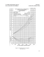
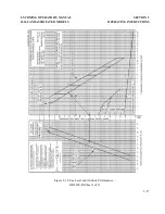
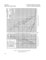
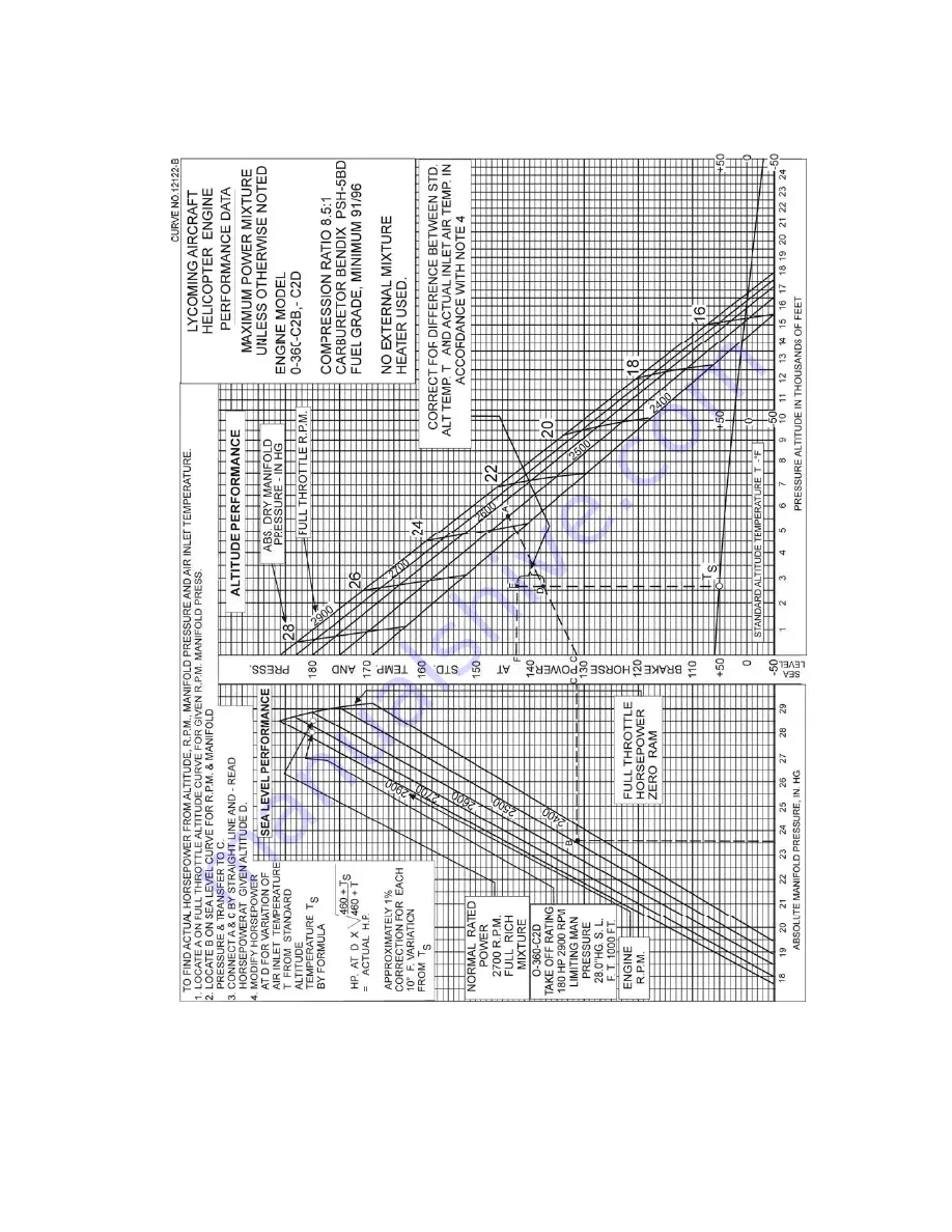
Figure 3-18. Sea Level and Altitude Performance – 

O-360-C2B, -C2D

3-33

Summary of Contents for AIO-360 Series

Page 1: ...his edition is a complete manual current as of the date of issue The manual incorporates all previously issued revisions This manual will be kept current by revisions available from Lycoming distributors or from the factory All revisions will be accompanied by an Operator s Manual Revision page which will identify the revision level the date of the revision and the pages revised added or deleted A...

Page 2: ...Operator s Manual Lycoming O 360 HO 360 IO 360 AIO 360 HIO 360 TIO 360 Series Approved by FAA 8th Edition Part No 60297 12 652 Oliver Street Williamsport PA 17701 U S A October 2005 570 323 6181 ...

Page 3: ... s in this revision replace add to or delete current pages in the operator s manual PREVIOUS REVISION CURRENT REVISION June 2007 Web Page 3 38 September 2007 3 8 3 9 3 11 December 2007 3 4 3 5 March 2009 1 5 Section 2 Index 2 3 2 8 2 11 3 5 3 21 3 41 2009 by Lycoming All Rights Reserved Lycoming Engines a division of AVCO Corporation a wholly owned subsidiary of Textron Inc ...

Page 4: ...60297 12 3 O 360 HO 360 IO 360 AIO 360 HIO 360 TIO 360 Series 60297 12 October 2005 The page s in this revision replace add to or delete current pages in the operator s manual PREVIOUS REVISION CURRENT REVISION June 2007 Web Page 3 38 September 2007 3 8 3 9 3 11 December 2007 3 4 3 5 ...

Page 5: ...ATION DATE 60297 12 2 O 360 HO 360 IO 360 AIO 360 HIO 360 TIO 360 Series 60297 12 October 2005 The page s in this revision replace add to or delete current pages in the operator s manual PREVIOUS REVISION CURRENT REVISION June 2007 Web Page 3 38 September 2007 3 8 3 9 3 11 ...

Page 6: ...ON NO PUBLICATION DATE 60297 12 1 O 360 HO 360 IO 360 AIO 360 HIO 360 TIO 360 Series 60297 12 October 2005 The page s in this revision replace add to or delete current pages in the operator s manual PREVIOUS REVISION CURRENT REVISION None June 2007 Web Page 3 38 ...

Page 7: ...is publication are trademarks or registered trademarks of their respective companies For additional information Mailing address Lycoming Engines 652 Oliver Street Williamsport PA 17701 U S A Phone Factory 570 323 6181 Sales Department 570 327 7268 Fax 570 327 7101 Lycoming s regular business hours are Monday through Friday from 8 00 AM through 5 00 PM Eastern Time 5 GMT Visit us on the World Wide ...

Page 8: ...RES CAN RESULT IN POOR ENGINE PERFORMANCE AND POWER LOSS ALSO IF POWER AND SPEED LIMITATIONS SPECIFIED IN THIS MANUAL ARE EXCEEDED FOR ANY REASON DAMAGE TO THE ENGINE AND PERSONAL INJURY CAN HAPPEN CONSULT YOUR LOCAL FAA APPROVED MAINTENANCE FACILITY SERVICE BULLETINS INSTRUCTIONS AND LETTERS Although the information contained in this manual is up to date at time of publication users are urged to ...

Page 9: ...rious Warnings and Cautions which must be carefully read in order to minimize the risk of personal injury or the use of improper service methods that may damage the engine or render it unsafe It is also important to understand that these Warnings and Cautions are not all inclusive Lycoming could not possibly know evaluate or advise the service trade of all conceivable ways in which service might b...

Page 10: ...to Lycoming s Warranty Administration within 60 days of being found to require repair or replacement by the purchaser or service facility Warranty adjustment is contingent upon the Purchaser complying with the Lycoming s Warranty Administration disposition instructions for defective parts Failure to comply with all of the terms of this paragraph may at Lycoming s sole option void this warranty 3 T...

Page 11: ...S UNDER IT IS BINDING UPON LYCOMING UNLESS IN WRITING AND SIGNED BY A DULY AUTHORIZED REPRESENTATIVE OF LYCOMING 6 All legal actions based upon claims or disputes pertaining to or involving this warranty including but not limited to Lycoming s denial of any claim or portion thereof under this warranty must be filed in the courts of general jurisdiction of Lycoming County Commonwealth of Pennsylvan...

Page 12: ...ECTION 1 DESCRIPTION 1 1 SECTION 2 SPECIFICATIONS 2 1 SECTION 3 OPERATING INSTRUCTIONS 3 1 SECTION 4 PERIODIC INSPECTIONS 4 1 SECTION 5 MAINTENANCE PROCEDURES 5 1 SECTION 6 TROUBLE SHOOTING 6 1 SECTION 7 INSTALLATION AND STORAGE 7 1 SECTION 8 TABLES 8 1 ...

Page 13: ...This Page Intentionally Left Blank ...

Page 14: ... Valve Operating Mechanism 1 1 Crankcase 1 1 Crankshaft 1 1 Connecting Rods 1 2 Pistons 1 2 Accessory Housing 1 2 Oil Sump 1 2 Cooling System 1 2 Induction System 1 2 Lubrication System 1 3 Priming System 1 3 Ignition System 1 3 Counterweight System 1 3 Model Application Table 1 3 ...

Page 15: ...This Page Intentionally Left Blank ...

Page 16: ... dual magnetos housed in a single housing Example All information pertinent to the O 360 A1F6 will apply to the O 360 A1F6D Operational aspects of engines are the same and performance curves and specifications for the basic model will apply Cylinders The cylinders are of conventional air cooled construction with the two major parts head and barrel screwed and shrunk together The heads are made fro...

Page 17: ...ar of the cowling Induction System Lycoming O 360 and HO 360 series engines are equipped with either a float type or pressure type carburetor See Table 1 for model application Particularly good distribution of the fuel air mixture to each cylinder is obtained through the center zone induction system which is integral with the oil sump and is submerged in oil insuring a more uniform vaporization of...

Page 18: ...l to the engine Lubrication System All models except AIO 360 series An impeller type pump contained within the accessory housing actuates the full pressure wet sump lubrication system AIO 360 Series The AIO 360 series is designed for aerobatic flying and is of the dry sump type A double scavenge pump is installed on the accessory housing Priming System Provision for a primer system is provided on ...

Page 19: ...MA 4 5 HA 6 HO 360 A1A B1A B1B C1A S4LN 200 S4LN 200 S4LN 200 4347 S4LN 204 S4LN 204 S4LN 200 4370 MA 4 5AA PSH 5BD PSH 5BD HA 6 HIO 360 A1A B1A B1B A1B C1A C1B D1A G1A S4LN 200 S4LN 200 S4LN 1208 S4LN 1208 4347 S4LN 200 S4LN 204 S4LN 1209 S4LN 1208 4370 Fuel Injector RSA 5AB1 RSA 5AD1 RSA 5AD1 RSA 7AA1 RSA 5AD1 HIO 360 Dual Magneto E1AD E1BD F1AD D4LN 3021 D4LN 3200 RSA 5AB1 RSA 5AB1 IO 360 A1A A...

Page 20: ...A1A A2A A1B A2B B1B S4LN 1208 S4LN 1227 S4LN 1209 S4LN 1209 RSA 5AD1 RSA 5AD1 TIO 360 A1A A1B A3B6 S4LN 1208 S4LN 1209 RSA 5AD1 TIO 360 Dual Magneto C1A6D D4LN 3021 RSA 5AD1 Models with counterclockwise rotation employ S4RN series See latest revision of Service Instruction No 1443 for alternate magnetos For information pertaining to engine model L IO 360 M1A refer to Operation and Installation Man...

Page 21: ...This Page Intentionally Left Blank ...

Page 22: ...G6 M1B 2 3 IO 360 A C D J K 2 3 IO 360 B E F 2 4 AIO 360 A B 2 4 HIO 360 A B 2 4 HIO 360 C 2 5 HIO 360 D 2 5 HIO 360 E 2 5 HIO 360 F1AD 2 6 HIO 360 G1A 2 6 TIO 360 A 2 6 TIO 360 C 2 7 Accessory Drives 2 7 Detail Weights 2 7 Dimensions 2 9 For information pertaining to engine model L IO 360 M1A refer to Operation and Installation Manual P N 60297 36 Revised March 2009 ...

Page 23: ...This Page Intentionally Left Blank ...

Page 24: ... 360 B D Series FAA Type Certificate 286 Rated horsepower 168 Rated speed RPM 2700 Bore inches 5 125 Stroke inches 4 375 Displacement cubic inches 361 0 Compression ratio 7 2 1 Firing order 1 3 2 4 Spark occurs degrees BTC 25 Valve rocker clearance hydraulic tappets collapsed 028 080 Propeller drive ratio 1 1 Propeller driven rotation viewed from rear Clockwise O 360 J2A FAA Type Certificate 286 R...

Page 25: ...Rated speed RPM 2900 Bore inches 5 125 Stroke inches 4 375 Displacement cubic inches 361 0 Compression ratio 8 5 1 Firing order 1 3 2 4 Spark occurs degrees BTC 25 Valve rocker clearance hydraulic tappets collapsed 028 080 Propeller drive ratio 1 1 Propeller driven rotation viewed from rear Clockwise IO 360 L2A FAA Type Certificate 1E10 Rated horsepower 160 Rated speed RPM 2400 Bore inches 5 125 S...

Page 26: ...Series FAA Type Certificate 1E10 Rated horsepower 200 Rated speed RPM 2700 Bore inches 5 125 Stroke inches 4 375 Displacement cubic inches 361 0 Compression ratio 8 7 1 Firing order 1 3 2 4 Spark occurs degrees BTC 25 Valve rocker clearance hydraulic tappets collapsed 028 080 Propeller drive ratio 1 1 Propeller driven rotation viewed from rear Clockwise NOTE On the following model engines the magn...

Page 27: ...375 Displacement cubic inches 361 0 Compression ratio 8 7 1 Firing order 1 3 2 4 Spark occurs degrees BTC 25 Valve rocker clearance hydraulic tappets collapsed 028 080 Propeller drive ratio 1 1 Propeller driven rotation viewed from rear Clockwise See Note Page 2 3 HIO 360 A B Series FAA Type Certificate 1E10 Rated horsepower 180 Rated speed RPM 2900 Bore inches 5 125 Stroke inches 4 375 Displaceme...

Page 28: ...nt cubic inches 361 0 Compression ratio 10 0 1 Firing order 1 3 2 4 Spark occurs degrees BTC 20 Valve rocker clearance hydraulic tappets collapsed 028 080 Propeller drive ratio 1 1 Propeller driven rotation viewed from rear Clockwise Consult Service Bulletin No 402 for valve rocker clearance of HIO 360 D1A HIO 360 E Series FAA Type Certificate 1E10 Rated horsepower 190 Rated speed RPM 2900 Bore in...

Page 29: ...te 1E10 Rated horsepower 180 Rated speed RPM 2700 Bore inches 5 125 Stroke inches 4 375 Displacement cubic inches 361 0 Compression ratio 8 5 1 Firing order 1 3 2 4 Spark occurs degrees BTC 25 Valve rocker clearance hydraulic tappets collapsed 028 080 Propeller drive ratio 1 1 Propeller drive rotation viewed from rear Clockwise TIO 360 A Series FAA Type Certificate E16EA Rated horsepower 200 Rated...

Page 30: ...Propeller Governor Rear Mounted 0 866 1 Clockwise Propeller Governor Front Mounted 0 895 1 Clockwise Fuel Pump AN20010 0 866 1 Counterclockwise Fuel Pump AN20003 1 000 1 Counterclockwise Fuel Pump Plunger Operated Dual Drives 0 500 1 Vacuum Hydraulic Pump 1 300 1 Counterclockwise Vacuum Prop Governor 1 300 1 Counterclockwise When applicable Viewed facing drive pad HIO 360 D1A Alternator drive is 2...

Page 31: ... 294 A4M A4P A1F6D C4F 295 A4K A4N A5AD 296 A4D A1G6D 297 A4A A1F6 A1H6 298 A4J A1G6 F1A6 300 A4G 301 G1A6 303 Weight does not include alternator HO 360 Series A1A 285 B1A B1B C1A 288 IO 360 Series L2A 278 B1C 289 B1A 295 B1E 296 B1D 297 B1B 299 M1B 300 B1F B2F 301 B1G6 305 B4A 307 B2F6 308 K2A 311 A1D6D A3D6D C1A 319 C1B 320 C1C D1A 322 J1AD 323 For information pertaining to engine model L IO 360...

Page 32: ...6 335 C1E6 337 AIO 360 Series A1A A2A 331 A1B A2B B1B 332 HIO 360 Series G1A 283 B1A B1B 290 A1A 311 A1B 312 D1A E1AD E1BD 321 C1A 322 C1B 323 F1AD 324 TIO 360 Series C1A6D 379 A1A A1B 386 A3B6 407 DIMENSIONS INCHES MODEL HEIGHT WIDTH LENGTH O 360 Series A1A A1P A2A A1C A1D A2D A1F A2F A1F6 A1G A2G A1H A2H 24 59 19 68 24 59 24 59 24 59 19 22 19 22 33 37 33 37 33 37 33 37 33 37 33 37 33 37 29 56 30...

Page 33: ...33 37 33 37 33 37 33 37 33 37 33 37 33 37 32 24 33 38 33 37 31 81 29 56 29 81 31 82 31 82 29 05 31 33 31 33 29 56 29 81 29 56 29 81 29 05 30 67 29 56 29 81 29 81 31 81 31 83 HO 360 Series A1A B1A B1B C1A 24 59 19 68 19 22 33 37 33 37 33 37 29 81 30 67 31 82 IO 360 Series A1A A2A A1D A1B A2B A1B6 A3B6 A1C A2C A1D6 A1B6D A3B6D J1AD A1D6D A3D6D B1A B1B B1D L2A B1C B1E B1F B2F B2F6 B4A C1A C1B C1C C1C...

Page 34: ... A1B A2B B1B 20 76 20 76 20 76 34 25 34 25 34 25 30 08 30 08 30 08 HIO 360 Series A1A A1B B1A B1B C1A C1B D1A G1A E1AD A1BD F1AD 19 48 19 38 19 38 19 48 19 48 19 68 19 97 35 25 33 37 33 37 34 25 35 25 33 37 34 25 33 65 32 09 30 68 31 14 35 28 31 81 31 36 TIO 360 Series A1A A1B A3B6 C1A6D 21 43 19 92 21 65 34 25 34 25 19 09 45 41 45 41 35 82 For information pertaining to engine model L IO 360 M1A r...

Page 35: ...This Page Intentionally Left Blank ...

Page 36: ...neral 3 1 Prestarting Items of Maintenance 3 1 Starting Procedures 3 1 Cold Weather Starting 3 3 Ground Running and Warm Up 3 3 Ground Check 3 4 Operation in Flight 3 5 Engine Flight Chart 3 10 Operating Conditions 3 11 Shut Down Procedure 3 16 Performance Curves 3 17 ...

Page 37: ...This Page Intentionally Left Blank ...

Page 38: ...s should be operated on straight mineral oil for a minimum of 50 hours or until oil consumption has stabilized After this period a change to an approved additive oil may be made if so desired NOTE Cruising should be done at 65 to 75 power until a total of 50 hours has accumulated or oil consumption has stabilized This is to ensure proper seating of the rings and is applicable to new engines and en...

Page 39: ... Both 12 Check oil pressure gage If minimum oil pressure is not indicated within thirty seconds stop engine and determine trouble b Engines Equipped with Pressure Carburetors or Bendix Fuel Injectors 1 Perform pre flight inspection 2 Set carburetor heat or alternate air control in Off position 3 Set propeller governor control in Full RPM position where applicable 4 Turn fuel valve On 5 Turn boost ...

Page 40: ... 8 Open throttle travel 9 Move combination magneto switch to Start using accelerator pump as a primer while cranking engine 10 When engine fires allow the switch to return to Both 11 Check oil pressure gage If minimum oil pressure is not indicated within thirty seconds stop engine and determine trouble 4 COLD WEATHER STARTING During extreme cold weather it may be necessary to preheat the engine an...

Page 41: ...d return to full low pitch position Full feathering check twin engine on the ground is not recommended but the feathering action can be checked by running the engine between 1000 1500 RPM then momentarily pulling the propeller control into the feathering position Do not allow the RPM to drop more than 500 RPM e A proper magneto check is important Additional factors other than the ignition system a...

Page 42: ... drop off past normal is usually a sign of a too lean or too rich mixture f Do not operate on a single magneto for too long a period a few seconds is usually sufficient to check drop off and to minimize plug fouling 7 OPERATION IN FLIGHT a See airframe manufacturer s instructions for recommended power settings b Throttle movements from full power to idle or from idle to full power are full range m...

Page 43: ...tings Operate the engine at maximum power mixture for performance cruise powers and at best economy mixture for economy cruise power unless otherwise specified in the airplane owner s manual During letdown flight operations it may be necessary to manually lean uncompensated carbureted or fuel injected engines to obtain smooth operation On turbocharged engines never exceed 1650 F turbine inlet temp...

Page 44: ...3 O 360 AND ASSOCIATED MODELS OPERATING INSTRUCTIONS Figure 3 1 Representative Effect of Fuel Air Ratio on Cylinder Head Temperature Power and Specific Fuel Consumption at Constant RPM and Manifold Pressure in Cruise Range Operation 3 7 ...

Page 45: ...oothly and power is regained WARNING REFER TO THE PILOT S OPERATING HANDBOOK OR AIRFRAME MANUFACTURER S MANUAL FOR ADDITIONAL INSTRUCTIONS ON THE USE OF CARBURETOR HEAT CONTROL INSTRUCTIONS FOUND IN EITHER PUBLICATION SUPERSEDE THE FOLLOWING INFORMATION c Use of Carburetor Heat Control Under certain moist atmospheric conditions generally at a relative humidity of 50 or greater and at temperatures ...

Page 46: ...ossible for engine roughness to occur due to the over rich fuel air mixture produced by the additional carburetor heat When this happens lean the mixture with the mixture control only enough to produce smooth engine operation Do not continue to use carburetor heat after flight is out of icing conditions and return mixture to full rich when carburetor heat is removed 4 Flight Operation During norma...

Page 47: ...60 A C D E F 100 130 TIO 360 A 100 130 NOTE Aviation grade 100LL fuels in which the lead content is limited to 2 c c per gal are approved for continuous use in the above listed engines Refer to latest revision of Service Instruction No 1070 FUEL PRESSURE PSI Model Max Desired Min O 360 Series Except A1C C2B C2D HO 360 A C Series Inlet to carburetor 8 0 3 0 0 5 O 360 A1C C2B C1D HO 360 B Series Inl...

Page 48: ... 50 30 to 90 F SAE 40 SAE 40 0 to 70 F SAE 30 SAE 40 30 or 20W40 Below 10 F SAE 20 SAE 30 or 20W30 Refer to latest revision of Service Instruction No 1014 OIL SUMP CAPACITY All Models Except AIO 360 Series O 360 J2A 8 U S Quarts Minimum Safe Quantity in Sump Except IO 360 M1A M1B HIO 360 G1A 2 U S Quarts IO 360 M1A M1B HIO 360 G1A 4 U S Quarts AIO 360 Series Dry Sump O 360 J2A 6 U S Quarts OPERATI...

Page 49: ...formance Cruise 75 Rated 2450 135 10 5 45 500 F 260 C Economy Cruise 65 Rated 2350 117 9 5 39 500 F 260 C O 360 B D Series Normal Rated 2700 168 75 500 F 260 C Performance Cruise 75 Rated 2450 126 11 6 42 500 F 260 C Economy Cruise 65 Rated 2350 109 9 0 37 500 F 260 C O 360 A1P A4D A4P C4P F G Series Normal Rated 2700 180 80 500 F 260 C Performance Cruise 75 Rated 2450 135 9 7 45 500 F 260 C Econo...

Page 50: ...60 B Series Normal Rated 2900 180 80 500 F 260 C Performance Cruise 75 Rated 2700 135 10 5 45 500 F 260 C Economy Cruise 65 Rated 2700 117 9 0 39 500 F 260 C IO 360 A C D J K AIO 360 Series Normal Rated 2700 200 89 500 F 260 C Performance Cruise 75 Rated 2450 150 12 3 50 500 F 260 C Economy Cruise 65 Rated 2350 130 9 5 44 500 F 260 C IO 360 B E F Series Except B1C IO 360 M1A M1B Normal Rated 2700 ...

Page 51: ...34 500 F 260 C HIO 360 A Series Normal Rated 2900 180 80 500 F 260 C Performance Cruise 75 Rated 2700 135 11 0 45 500 F 260 C Economy Cruise 65 Rated 2700 117 9 5 39 500 F 260 C HIO 360 B Series Normal Rated 2900 180 80 500 F 260 C Performance Cruise 75 Rated 2700 135 12 0 45 500 F 260 C Economy Cruise 65 Rated 2700 117 10 0 39 500 F 260 C HIO 360 C Series Normal Rated 2900 205 91 500 F 260 C Perf...

Page 52: ...0 F 260 C HIO 360 F Series Normal Rated 3050 190 84 500 F 260 C Performance Cruise 75 Rated 2700 142 11 8 47 500 F 260 C Economy Cruise 65 Rated 2700 123 10 0 46 500 F 260 C TIO 360 A Series Normal Rated 2700 200 89 500 F 260 C Performance Cruise 75 Rated 2450 150 14 0 50 500 F 260 C Economy Cruise 65 Rated 2350 130 10 2 44 500 F 260 C TIO 360 C Series Normal Rated 2575 210 70 500 F 260 C Performa...

Page 53: ...ngle when applicable 2 Idle until there is a decided drop in cylinder head temperature 3 Move mixture control to Idle Cut Off 4 When engine stops turn off switches b Helicopters 1 Idle as directed in the airframe manufacturer s handbook until there is a decided drop in cylinder head temperature 2 Move mixture control to Idle Cut Off 3 When engine stops turn off switches 3 16 ...

Page 54: ...LYCOMING OPERATOR S MANUAL SECTION 3 O 360 AND ASSOCIATED MODELS OPERATING INSTRUCTIONS Figure 3 2 Power Curve O 360 B D Series 3 17 ...

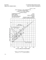
Page 55: ...SECTION 3 LYCOMING OPERATOR S MANUAL OPERATING INSTRUCTIONS O 360 AND ASSOCIATED MODELS Figure 3 3 Part Throttle Fuel Consumption O 360 C2B C2D 3 18 ...

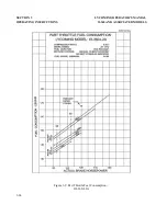
Page 56: ...LYCOMING OPERATOR S MANUAL SECTION 3 O 360 AND ASSOCIATED MODELS OPERATING INSTRUCTIONS Figure 3 4 Part Throttle Fuel Consumption HO 360 B Series 3 19 ...

Page 57: ...SECTION 3 LYCOMING OPERATOR S MANUAL OPERATING INSTRUCTIONS O 360 AND ASSOCIATED MODELS Figure 3 5 Part Throttle Fuel Consumption IO 360 A C D J K AIO 360 Series 3 20 ...

Page 58: ...LS OPERATING INSTRUCTIONS Figure 3 6 Part Throttle Fuel Consumption IO 360 B E F M1B Series Excepting IO 360 B1A B1C HIO 360 G1A For information pertaining to engine model L IO 360 M1A refer to Operation and Installation Manual P N 60297 36 Revised March 2009 3 21 ...

Page 59: ...SECTION 3 LYCOMING OPERATOR S MANUAL OPERATING INSTRUCTIONS O 360 AND ASSOCIATED MODELS Figure 3 7 Part Throttle Fuel Consumption IO 360 B1A 3 22 ...

Page 60: ...LYCOMING OPERATOR S MANUAL SECTION 3 O 360 AND ASSOCIATED MODELS OPERATING INSTRUCTIONS Figure 3 8 Part Throttle Fuel Consumption IO 360 B1C 3 23 ...

Page 61: ...SECTION 3 LYCOMING OPERATOR S MANUAL OPERATING INSTRUCTIONS O 360 AND ASSOCIATED MODELS Figure 3 9 Part Throttle Fuel Consumption IO 360 L2A 3 24 ...

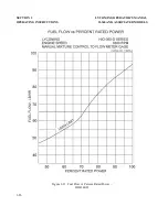
Page 62: ...LYCOMING OPERATOR S MANUAL SECTION 3 O 360 AND ASSOCIATED MODELS OPERATING INSTRUCTIONS Figure 3 10 Fuel Flow vs Percent Rated Power TIO 360 A Series 3 25 ...

Page 63: ...SECTION 3 LYCOMING OPERATOR S MANUAL OPERATING INSTRUCTIONS O 360 AND ASSOCIATED MODELS Figure 3 11 Fuel Flow vs Percent Rated Power HIO 360 D 3 26 ...

Page 64: ...LYCOMING OPERATOR S MANUAL SECTION 3 O 360 AND ASSOCIATED MODELS OPERATING INSTRUCTIONS Figure 3 12 Sea Level and Altitude Performance HIO 360 D Sheet 1 of 2 3 27 ...

Page 65: ...SECTION 3 LYCOMING OPERATOR S MANUAL OPERATING INSTRUCTIONS O 360 AND ASSOCIATED MODELS Figure 3 13 Sea Level and Altitude Performance HIO 360 D Sheet 2 of 2 3 28 ...

Page 66: ...LYCOMING OPERATOR S MANUAL SECTION 3 O 360 AND ASSOCIATED MODELS OPERATING INSTRUCTIONS Figure 3 14 Fuel Flow vs Percent Rated Power HIO 360 A Series 3 29 ...

Page 67: ...SECTION 3 LYCOMING OPERATOR S MANUAL OPERATING INSTRUCTIONS O 360 AND ASSOCIATED MODELS Figure 3 15 Fuel Flow vs Percent Rated Power HIO 360 B Series 3 30 ...

Page 68: ...LYCOMING OPERATOR S MANUAL SECTION 3 O 360 AND ASSOCIATED MODELS OPERATING INSTRUCTIONS Figure 3 16 Fuel Flow vs Percent Rated Power HIO 360 C Series 3 31 ...

Page 69: ...SECTION 3 LYCOMING OPERATOR S MANUAL OPERATING INSTRUCTIONS O 360 AND ASSOCIATED MODELS Figure 3 17 Sea Level and Altitude Performance O 360 A C Except those listed for Figure 3 40 HIO 360 A Series 3 32 ...

Page 70: ...LYCOMING OPERATOR S MANUAL SECTION 3 O 360 AND ASSOCIATED MODELS OPERATING INSTRUCTIONS Figure 3 18 Sea Level and Altitude Performance O 360 C2B C2D 3 33 ...

Page 71: ...SECTION 3 LYCOMING OPERATOR S MANUAL OPERATING INSTRUCTIONS O 360 AND ASSOCIATED MODELS Figure 3 19 Sea Level and Altitude Performance O 360 B D Series 3 34 ...

Page 72: ...LYCOMING OPERATOR S MANUAL SECTION 3 O 360 AND ASSOCIATED MODELS OPERATING INSTRUCTIONS Figure 3 20 Sea Level and Altitude Performance HO 360 B Series 3 35 ...

Page 73: ...SECTION 3 LYCOMING OPERATOR S MANUAL OPERATING INSTRUCTIONS O 360 AND ASSOCIATED MODELS Figure 3 21 Sea Level and Altitude Performance IO 360 A C D J K AIO 360 Series 3 36 ...

Page 74: ...LYCOMING OPERATOR S MANUAL SECTION 3 O 360 AND ASSOCIATED MODELS OPERATING INSTRUCTIONS Figure 3 22 Sea Level and Altitude Performance IO 360 B E F Series Excepting IO 360 B1A B1C HIO 360 G1A 3 37 ...

Page 75: ...SECTION 3 LYCOMING OPERATOR S MANUAL OPERATING INSTRUCTIONS O 360 AND ASSOCIATED MODELS Figure 3 23 Sea Level and Altitude Performance IO 360 B1A 3 38 Revised June 2007 ...

Page 76: ...LYCOMING OPERATOR S MANUAL SECTION 3 O 360 AND ASSOCIATED MODELS OPERATING INSTRUCTIONS Figure 3 24 Sea Level and Altitude Performance IO 360 B1C 3 39 ...

Page 77: ...SECTION 3 LYCOMING OPERATOR S MANUAL OPERATING INSTRUCTIONS O 360 AND ASSOCIATED MODELS Figure 3 25 Sea Level and Altitude Performance IO 360 L2A 3 40 ...

Page 78: ...60 AND ASSOCIATED MODELS OPERATING INSTRUCTIONS Figure 3 26 Sea Level and Altitude Performance IO 360 M1B For information pertaining to engine model L IO 360 M1A refer to Operation and Installation Manual P N 60297 36 Revised March 2009 3 41 ...

Page 79: ...SECTION 3 LYCOMING OPERATOR S MANUAL OPERATING INSTRUCTIONS O 360 AND ASSOCIATED MODELS Figure 3 28 Sea Level and Altitude Performance HIO 360 A Series 3 42 ...

Page 80: ...LYCOMING OPERATOR S MANUAL SECTION 3 O 360 AND ASSOCIATED MODELS OPERATING INSTRUCTIONS Figure 3 29 Sea Level and Altitude Performance HIO 360 B Series 3 43 ...

Page 81: ...SECTION 3 LYCOMING OPERATOR S MANUAL OPERATING INSTRUCTIONS O 360 AND ASSOCIATED MODELS Figure 3 30 Sea Level and Altitude Performance HIO 360 C Series 3 44 ...

Page 82: ...LYCOMING OPERATOR S MANUAL SECTION 3 O 360 AND ASSOCIATED MODELS OPERATING INSTRUCTIONS Figure 3 31 Sea Level and Altitude Performance TIO 360 A Series Sheet 1 of 5 3 45 ...

Page 83: ...SECTION 3 LYCOMING OPERATOR S MANUAL OPERATING INSTRUCTIONS O 360 AND ASSOCIATED MODELS Figure 3 32 Sea Level and Altitude Performance TIO 360 A Series Sheet 2 of 5 3 46 ...

Page 84: ...LYCOMING OPERATOR S MANUAL SECTION 3 O 360 AND ASSOCIATED MODELS OPERATING INSTRUCTIONS Figure 3 33 Sea Level and Altitude Performance TIO 360 A Series Sheet 3 of 5 3 47 ...

Page 85: ...SECTION 3 LYCOMING OPERATOR S MANUAL OPERATING INSTRUCTIONS O 360 AND ASSOCIATED MODELS Figure 3 34 Sea Level and Altitude Performance TIO 360 A Series Sheet 4 of 5 3 48 ...

Page 86: ...LYCOMING OPERATOR S MANUAL SECTION 3 O 360 AND ASSOCIATED MODELS OPERATING INSTRUCTIONS Figure 3 35 Sea Level and Altitude Performance TIO 360 A Series Sheet 5 of 5 3 49 ...

Page 87: ...SECTION 3 LYCOMING OPERATOR S MANUAL OPERATING INSTRUCTIONS O 360 AND ASSOCIATED MODELS Figure 3 36 Fuel Flow vs Percent Rated Power HIO 360 E F Series 3 50 ...

Page 88: ...LYCOMING OPERATOR S MANUAL SECTION 3 O 360 AND ASSOCIATED MODELS OPERATING INSTRUCTIONS Figure 3 37 Sea Level and Altitude Performance HIO 360 E Series 3 51 ...

Page 89: ...SECTION 3 LYCOMING OPERATOR S MANUAL OPERATING INSTRUCTIONS O 360 AND ASSOCIATED MODELS Figure 3 38 Sea Level and Altitude Performance with Turbocharger Kit SK 28 12100 HIO 360 E Series 3 52 ...

Page 90: ...LYCOMING OPERATOR S MANUAL SECTION 3 O 360 AND ASSOCIATED MODELS OPERATING INSTRUCTIONS Figure 3 39 Fuel Flow vs Percent Rated Power O 360 A C F G Series HO 360 C1A 3 53 ...

Page 91: ...SECTION 3 LYCOMING OPERATOR S MANUAL OPERATING INSTRUCTIONS O 360 AND ASSOCIATED MODELS Figure 3 40 Fuel Flow vs Percent Rated Power O 360 J2A 3 54 ...

Page 92: ...LYCOMING OPERATOR S MANUAL SECTION 3 O 360 AND ASSOCIATED MODELS OPERATING INSTRUCTIONS Figure 3 41 Sea Level and Altitude Performance O 360 J2A 3 55 ...

Page 93: ...G OPERATOR S MANUAL OPERATING INSTRUCTIONS O 360 AND ASSOCIATED MODELS Figure 3 42 Sea Level and Altitude Performance O 360 A1A A1D A1P A2A A2D A2F A3A A4A A4D A4M A4N A4P A1F6 A1H6 C1F C1G C4F C4P F1A6 HO 360 C1A 3 56 ...

Page 94: ...LYCOMING OPERATOR S MANUAL SECTION 3 O 360 AND ASSOCIATED MODELS OPERATING INSTRUCTIONS Figure 3 43 Sea Level and Altitude Performance HIO 360 F Series 3 57 ...

Page 95: ...SECTION 3 LYCOMING OPERATOR S MANUAL OPERATING INSTRUCTIONS O 360 AND ASSOCIATED MODELS Figure 3 44 Sea Level and Altitude Performance with Turbocharger Kit SK 28 121000 HIO 360 F Series 3 58 ...

Page 96: ...LYCOMING OPERATOR S MANUAL SECTION 3 O 360 AND ASSOCIATED MODELS OPERATING INSTRUCTIONS Figure 3 45 Fuel Flow vs Brake Horsepower TIO 360 C1A6D 3 59 ...

Page 97: ...SECTION 3 LYCOMING OPERATOR S MANUAL OPERATING INSTRUCTIONS O 360 AND ASSOCIATED MODELS Figure 3 46 Sea Level and Altitude Performance TIO 360 C1A6D Sheet 1 of 3 3 60 ...

Page 98: ...LYCOMING OPERATOR S MANUAL SECTION 3 O 360 AND ASSOCIATED MODELS OPERATING INSTRUCTIONS Figure 3 47 Sea Level and Altitude Performance TIO 360 C1A6D Sheet 2 of 3 3 61 ...

Page 99: ...SECTION 3 LYCOMING OPERATOR S MANUAL OPERATING INSTRUCTIONS O 360 AND ASSOCIATED MODELS Figure 3 48 Sea Level and Altitude Performance TIO 360 C1A6D Sheet 3 of 3 3 62 ...

Page 100: ...n but are meant for the engine only Consult the airframe manufacturer s handbookfor additional instructions Pre Starting Items of Maintenance The daily pre flight inspection is a checkof the aircraft prior to the first flight of the day The inspection is to determine the general condition of the aircraft and engine The importance of proper pre flight inspection cannot be over emphasiz ed Statistic...

Page 101: ... security lubricant or air leak age 2 Checkengine crank case breather for restrictions to breather 2 25 HOUR INSPECTION ENGINE After the first twenty five hours operation time new rebuilt or newly overhauled engines should undergo a 50 hour inspection including draining and renewing lubricating oil If engine has no full flow oil filter change oil every 25 hours Also inspect and clean suction and p...

Page 102: ...oose they must be removed and machined flat before they are reassembled and tightened Ex amine ex haust manifolds for general condition e Cooling System Check cowling and baffle for damage and secure anchorage Any damaged or missing part of the cooling system must be repaired or replaced before the aircraft resumes operation f Cylinders Checkrock er boxcover for evidence of oil leak s If found rep...

Page 103: ...s instructions Checkmagneto to engine timing Timing procedure is described in Section 5 1 b of this manual d Engine Accessories Engine mounted accessories such as pumps temperature and pressure sensing units should be check ed for secure mounting tight connections e Cylinders Checkcylinders visually for crack ed or brok en fins f Engine Mounts Checkengine mounting bolts and bushings for security a...

Page 104: ...g the piston and connecting rod assembly and inspected for further damage Replace any parts that do not conform with limits shown in the latest revision of Special Service Publication No SSP1776 6 NON SCHEDULED INSPECTIONS Occasionally Service Bulletins or Service Instructions are issued by Lycoming that req uire inspection procedures that are not listed in this manual Such publications usually ar...

Page 105: ...This Page Intentionally Left Blank ...

Page 106: ...r Alternator Output 5 4 Fuel System Repair of Fuel Leaks 5 4 Carburetor or Fuel Injector Inlet Screen Assembly 5 4 Fuel Grades and Limitations 5 4 Air Intake Ducts and Filter 5 4 Idle Speed and Mixture Adjustment 5 4 Lubrication System Oil Grades and Limitations 5 4 Oil Suction and Oil Pressure Screens 5 5 Oil Pressure Relief Valve 5 5 Cylinders 5 5 Generator or Alternator Drive Belt Tension 5 9 T...

Page 107: ...This Page Intentionally Left Blank ...

Page 108: ...nd turn the drive shaft in direction of normal rotation until 20 and 200 series the first painted chamfered tooth on the distributor gear is aligned in the center of the inspection window 1200 series the applicable timing markon the distributor gear is approx imately aligned with the markon the distributor block See Figure 5 2 Being sure the gear does not move from this position install gask ets a...

Page 109: ...SECTION 5 LYCOMING OPERATOR S MANUAL MAINTENANCE PROCEDURES O 360 AND ASSOCIATED MODELS Figure 5 1 Ignition Wiring Diagram Figure 5 2 Timing Mark s 4 Cylinder 1200 Series 5 2 ...

Page 110: ...al and the second positive lead to the right main break er terminal 2 Backthe engine up a few degrees and again bump forward toward number one cylinder firing position while observing timing lights Both lights should go out to indicate opening of the main break ers when the timing pointer is indicating within the width of the L or R mark If break er timing is incorrect loosen break er screws and c...

Page 111: ...l Fuel of a lower octane than specified is not to be used Under no circumstances should automotive fuel be used regardless of octane rating NOTE It is recommended that personnel be familiar with latest revision of Service Instruction No 1070 regarding specified fuel for Lycoming engines d Air Intake Ducts and Filter Checkall air intak e ducts for dirt or restrictions Inspect and service air filter...

Page 112: ... to maintain engine oil pressure within specified limits The valve although not adj ustable may control the oil pressure with the addition of a max imum of nine 9 P N STD 425 washers between the cap and spring to increase the pressure Removal of the washers will decrease the oil pressure Some early model engines use a max imum of three 3 P N STD 425 washers to increase the oil pressure and the use...

Page 113: ...on to drop against the crank case as the piston leaves the cylinder b Removal of Piston from Connecting Rod Remove the piston pin plugs Insert piston pin puller through piston pin assemble puller nut then proceed to remove piston pin Do not allow connecting rod to rest on the cylinder bore of the crank case Support the connecting rod with heavy rubber band discarded cylinder base oil ring seal or ...

Page 114: ...fit If difficulty is ex perienced in inserting the piston pin it is probably caused by carbon or burrs in the piston pin hole During assembly always use a generous q uantity of oil both in the piston hole and on the piston pin 3 Assemble one piston pin plug at each end of the piston pin and place a new rubber oil seal ring around the cylinder sk irt Coat piston and rings and the inside of the cyli...

Page 115: ... tighten the inch cylinder base nuts to 600 in lbs 50 ft lbs torq ue NOTE Cylinder assemblies not using hold down plate are tightened in the same manner as above omitting the shims Figure 5 3 Location of Shims Between Cylinder Barrel and Hold Down Plates where applicable and Seq uence of Tightening Cylinder Base Hold Down Nuts 5 8 ...

Page 116: ...the end of the push rod and push down so as to compress the hydraulic tappet spring While holding the spring compressed the valve clearance should be between 028and 08 0 inch If clearance does not come within these limits remove the push rod and insert a longer or shorter push rod as req uired to correct clearance NOTE Inserting a longer push rod will decrease the valve clearance 9 Install intercy...

Page 117: ...oil pressure and is set to predetermined open and closed clearances These clearances and the procedures for setting them are shown in Figure 5 5 Exhaust Bypass Valve TIO 360 C1A6D This valve is mechanically controlled by a flex ible link age connected to the inj ector throttle arm and the wastegate control arm Adj ust link age as follows 1 Move inj ector throttle arm to full open position 2 Insert...

Page 118: ...LYCOMING OPERATOR S MANUAL SECTION 5 O 360 AND ASSOCIATED MODELS MAINTENANCE PROCEDURES Figure 5 4 Density Control Full Throttle Setting Limits 5 11 ...

Page 119: ...SECTION 5 LYCOMING OPERATOR S MANUAL MAINTENANCE PROCEDURES O 360 AND ASSOCIATED MODELS Figure 5 5 Ex haust Bypass Valve Open and Closed Setting Figure 5 6 Timing Mark s on Rotating Magnet 5 12 ...

Page 120: ...LYCOMING OPERATOR S MANUAL SECTION 5 O 360 AND ASSOCIATED MODELS MAINTENANCE PROCEDURES Figure 5 7 Ignition Wiring Diagram Dual Magneto 5 13 ...

Page 121: ...This Page Intentionally Left Blank ...

Page 122: ...Uneven Running 6 2 Failure of Engine to Develop Full Power 6 3 Rough Engine 6 3 Low Oil Pressure 6 3 High Oil Temperature 6 3 Excessive Oil Consumption 6 4 TROUBLE SHOOTING TURBOCHARGER Excessive Noise or Vibration 6 4 Engine Will Not Deliver Rated Power 6 4 Critical Altitude Lower Than Specified 6 5 Engine Surges or Smokes 6 6 High Deck Pressure 6 6 ...

Page 123: ...This Page Intentionally Left Blank ...

Page 124: ...fuel tank Clean dirty lines strainers or fuel valves Overpriming Leave ignition off and mix ture control in Idle Cut Off open throttle and unload engine by crank ing for a few seconds Turn ignition switch on and proceed to start in a normal manner Defective sparkplugs Clean and adj ust or replace spark plugs Defective ignition wire Checkwith electric tester and replace any defective wires Defectiv...

Page 125: ...stment of fuel inj ector or sluggish engine operation red carburetor by authoriz ed ex haust flame at night Ex treme personnel is indicated cases indicated by blacksmok e from ex haust Mix ture too lean indicated by Checkfuel lines for dirt or other overheating or back firing restrictions Readj ustment of fuel inj ector or carburetor by author iz ed personnel is indicated Leak s in induction syste...

Page 126: ...on timing Rough Engine Crack ed engine mount Replace or repair mount Defective mounting bushings Install new mounting bushings Uneven compression Checkcompression Low Oil Pressure Insufficient oil Fill to proper level with recommended oil Air lockor dirt in relief valve Remove and clean oil pressure relief valve Leakin suction line or pressure Checkgask et between accessory line housing and crank ...

Page 127: ...of piston Install new rings rings Failure of rings to seat new Use mineral base oil Climb to nitrided cylinders cruise altitude at full power and operate at 75 cruise power setting until oil consumption stabiliz es 2 TROUBLE SHOOTING TURBOCHARGER TROUBLE PROBABLE CAUSE REMEDY Ex cessive Noise or Vibration Improper bearing lubrication Supply req uired oil pressure Clean or replace oil line clean oi...

Page 128: ...orifice Ex haust bypass controller Replace unit malfunction Ex haust bypass butterfly not Low pressure Clogged orifice in closing inlet to actuator Butterfly shaft binding Check bearings Turbocharger impeller binding Checkbearings Replace froz en or fouling housing turbocharger Piston seal in actuator leak ing Remove and replace actuator or Usually accompanied by oil disassemble and replace pack i...

Page 129: ...e aneroid bellows Ex haust bypass stick ing closed Shut off valve in return line not work ing Butterfly shaft binding Check bearings Replace bypass valve or correct link age binding Controller return line restricted Clean or replace line Oil pressure too high Checkpressure 75 to 8 5 psi 8 0 psi desired at ex haust bypass actuator desired If pressure on outlet side of actuator is too high have ex h...

Page 130: ...or Installation 7 1 General 7 1 Inspection of Engine Mounting 7 1 Attaching Engine to Mounts 7 1 Oil and Fuel Line Connections 7 1 Propeller Installation 7 2 Preparation of Carburetors and Fuel Injectors for Installation 7 2 Corrosion Prevention in Engines Installed in Inactive Aircraft 7 2 ...

Page 131: ...This Page Intentionally Left Blank ...

Page 132: ...n the lubricating oil should be drained while the engine is hot This will remove any residual preservative oil that may have been present CAUTION DO NOT ROTATE THE CRANKSHAFT OF AN ENGINE CONTAINING PRESERVATIVE OIL BEFORE REMOVING THE SPARK PLUGS BECAUSE IF THE CYLINDERS CONTAIN ANY APPRECIABLE AMOUNT OF THE MIXTURE THE RESULTING ACTION KNOWN AS HYDRAULICING WILL CAUSE DAMAGE TO THE ENGINE ALSO A...

Page 133: ...l flows from the discharge noz z le CAUTION DO NOT ALLOW FUEL OR OIL TO ENTER INTO THE AIR CHAMBER Move the throttle lever to the closed position and the mix ture control lever to the idle cut off position Because this carburetor has a closed fuel system it will remain full of fuel as long as the mix ture control lever is in the idle cut off position NOTE It is necessary that this carburetor soak ...

Page 134: ...air line of a conventional spray gun and be certain oil is hot at the nozzle before spraying cylinders d With the crank shaft stationary again spray each cylinder through the spark plug holes with approx imately two 2 ounces of corrosion preventive oil Assemble spark plugs and do not turn crank shaft after cylinders have been sprayed The corrosion preventive oil to be used in the foregoing procedu...

Page 135: ...SECTION 7 LYCOMING OPERATOR S MANUAL INSTALLATION AND STORAGE O 360 AND ASSOCIATED MODELS Figure 7 1 Fuel Metering System 7 4 ...

Page 136: ...LYCOMING OPERATOR S MANUAL SECTION 7 O 360 AND ASSOCIATED MODELS INSTALLATION AND STORAGE Figure 7 2 Magneto Connections 7 5 ...

Page 137: ...SECTION 7 LYCOMING OPERATOR S MANUAL INSTALLATION AND STORAGE O 360 AND ASSOCIATED MODELS Figure 7 3 Optional Oil Cooler Connections 7 6 ...

Page 138: ...LYCOMING OPERATOR S MANUAL SECTION 7 O 360 AND ASSOCIATED MODELS INSTALLATION AND STORAGE Figure 7 4 Installation Drawing O 360 A B Series Ex cept A1C A1G 7 7 ...

Page 139: ...SECTION 7 LYCOMING OPERATOR S MANUAL INSTALLATION AND STORAGE O 360 AND ASSOCIATED MODELS Figure 7 5 Installation Drawing O 360 A1C IO 360 B1C 7 8 ...

Page 140: ...LYCOMING OPERATOR S MANUAL SECTION 7 O 360 AND ASSOCIATED MODELS INSTALLATION AND STORAGE Figure 7 6 Installation Drawing O 360 C D Series Ex cept C2B C2D 7 9 ...

Page 141: ...SECTION 7 LYCOMING OPERATOR S MANUAL INSTALLATION AND STORAGE O 360 AND ASSOCIATED MODELS Figure 7 7 Installation Drawing O 360 C1B C1D HO 360 B1A B1B 7 10 ...

Page 142: ...LYCOMING OPERATOR S MANUAL SECTION 7 O 360 AND ASSOCIATED MODELS INSTALLATION AND STORAGE Figure 7 8 Installation Drawing IO 360 A Series 7 11 ...

Page 143: ...SECTION 7 LYCOMING OPERATOR S MANUAL INSTALLATION AND STORAGE O 360 AND ASSOCIATED MODELS Figure 7 9 Installation Drawing IO 360 B1A 7 12 ...

Page 144: ...LYCOMING OPERATOR S MANUAL SECTION 7 O 360 AND ASSOCIATED MODELS INSTALLATION AND STORAGE Figure 7 10 Installation Drawing IO 360 B1B B1D 7 13 ...

Page 145: ...SECTION 7 LYCOMING OPERATOR S MANUAL INSTALLATION AND STORAGE O 360 AND ASSOCIATED MODELS Figure 7 11 Installation Drawing IO 360 C1A C1B D1A HIO 360 C1A C1B 7 14 ...

Page 146: ...LYCOMING OPERATOR S MANUAL SECTION 7 O 360 AND ASSOCIATED MODELS INSTALLATION AND STORAGE Figure 7 12 Installation Drawing HIO 360 A1A 7 15 ...

Page 147: ...SECTION 7 LYCOMING OPERATOR S MANUAL INSTALLATION AND STORAGE O 360 AND ASSOCIATED MODELS Figure 7 13 Installation Drawing HIO 360 B1A B1B 7 16 ...

Page 148: ... TABLES Page Table of Limits 8 1 Ground Run After Top Overhaul 8 2 Flight Test After Top Overhaul 8 3 Full Throttle HP at Altitude 8 4 Table of Speed Equivalents 8 4 Centigrade Fahrenheit Conversion Table 8 5 Inch Fraction Conversions 8 6 ...

Page 149: ...This Page Intentionally Left Blank ...

Page 150: ...OMMENDATIONS AND INFORMATION CONCERNING TOLERANCES AND DIMENSIONS THAT MUST BE MAINTAINED IN LYCOMING AIRCRAFT ENGINES CONSULT THE LATEST EDITION OF SPECIAL SERVICE PUBLICATION NO SSP 1776 CONSULT LATEST REVISION OF SERVICE INSTRUCTION NO 1029 FOR INFORMATION PERTINENT TO CORRECTLY INSTALLING CYLINDER ASSEMBLY 8 1 ...

Page 151: ...SECTION 8 LYCOMING OPERATOR S MANUAL TABLES O 360 AND ASSOCIATED MODELS 8 2 ...

Page 152: ...LYCOMING OPERATOR S MANUAL SECTION 8 O 360 AND ASSOCIATED MODELS TABLES 8 3 ...

Page 153: ...000 58 7 22 000 44 0 4 000 8 7 5 16 000 56 5 22 500 43 3 5 000 8 4 6 17 000 54 3 23 000 42 2 6 000 8 1 7 17 500 53 1 23 500 41 4 7 000 78 9 18 000 52 1 24 000 40 3 8 000 76 2 18 500 51 4 24 500 39 5 9 000 73 5 19 000 50 0 25 000 38 5 TABLE OF SPEED EQUIVALENTS Sec Mi M P H Sec Mi M P H Sec Mi M P H 72 0 50 24 0 150 14 4 250 60 0 60 22 5 160 13 8 260 51 4 70 21 2 170 13 3 270 45 0 8 0 20 0 18 0 12 ...

Page 154: ...37 78 28 0 536 0 17 8 0 32 0 143 33 290 554 0 12 22 10 50 0 148 8 9 300 572 0 6 67 20 68 0 154 44 310 590 0 1 11 30 8 6 0 160 00 320 608 0 4 44 40 104 0 165 56 330 626 0 10 00 50 122 0 171 11 340 644 0 15 56 60 140 0 176 67 350 662 0 21 11 70 158 0 18 2 22 360 68 0 0 26 67 8 0 176 0 18 7 78 370 698 0 32 22 90 194 0 193 33 38 0 716 0 37 78 100 212 0 198 8 9 390 734 0 43 33 110 230 0 204 44 400 752 ...

Page 155: ...969 21 32 6562 338 2 16 669 11 64 1719 0232 4 366 43 64 6719 3545 17 065 3 16 18 75 0276 4 762 11 16 68 75 3712 17 462 7 32 218 7 0376 5 556 23 32 718 7 4057 18 256 15 64 2344 0431 5 593 47 64 7344 4235 18 653 1 4 25 0491 6 350 3 4 75 4418 19 050 9 32 28 12 0621 7 144 25 32 78 12 4794 19 8 44 19 64 2969 0692 7 540 51 64 7969 498 7 20 241 5 16 3125 0767 7 937 13 16 8 125 518 5 20 637 11 32 3437 092...

Reviews: