background image


TEO-540-C1A Engine Maintenance Manual


List of Tables


© 2022 Avco Corporation. All Rights Reserved


Page viii 


August 2022 

Field Service Tool User Manual


Warning, Cautions, and Notices 

Be sure to read and obey the Warnings, Cautions and Notices in this publication and in service 

documents. Although Lycoming cannot know all possible hazards or damages, it makes a reasonable 

effort to supply the best possible guidance and recommended practices for safe operation and 

maintenance of its engines. 
The table below defines the four types of safety advisory messages used in this publication per the 

American National Standard and ANSI Z535-6-2006. 

Safety Advisory Conventions 

Advisory Word 

Definition 

DANGER: 

Indicates a hazardous situation which, if not avoided, will result 

in death or serious injury. This signal word is to be limited to the 

most extreme situations. 


WARNING


Indicates a hazardous situation which, if not avoided, could 

result in death or serious injury. 


CAUTION


Indicates a hazardous situation which, if not avoided, could 

result in minor or moderate injury. It can also be used without 

the safety alert symbol as an alternative to 

"NOTICE." 

NOTICE: 

The preferred signal word to address practices not related to 

personal injury. 

Simplified Technical English 

The text in the publication is written in the form of Simplified Technical English in compliance with 

FAA requirements and to make translation into other languages easier. 

Figures 

Figures in this publication are for conceptual illustrative purposes only. Figures always start as 

Figure 1 in each chapter.


Copyright 

This publication is a copyrighted work. All rights reserved by Lycoming Engines. Content in this 

publication cannot be changed or released as a reprint, electronic media output, or web communiqué 

without written permission from Lycoming Engines. 

Supplemental Service Information 

Refer to the latest revision of Service Letter No. L114 for a list of Lycoming publications available 

for purchase. 

Feedback 

To supply comments, suggestions, or corrections to this publication, either call Lycoming Engines 

Customer Service at the phone number in the front of this publication or use the Lycoming.com 

website. 

Publication Revisions 

Lycoming Engines constantly examines our publications to provide our customers the most complete 

and up-to-date information for operating and maintaining our engines. Revisions to this publication 

will be published as necessary.

Summary of Contents for TEO-540 Series

Page 1: ... 2022 Avco Corporation All Rights Reserved Field Service Tool User Manual Troubleshooting Guide TEO 540 Series Engine Models August 2022 Part No SSP 122 ...

Page 2: ...echnicalsupport lycoming com Lycoming s regular business hours are Monday through Friday from 8 00AM through 5 00PM Eastern Time 5 GMT Visit us Online www lycoming com The information in this User Manual and Troubleshooting Guide is intended for general use of the FST as a diagnostic tool for TEO 540 Series engines If available refer to the model specific engine maintenance manual when identifying...

Page 3: ...poration All Rights Reserved Record of Revisions August 2022 Page i Field Service Tool User Manual RECORD OF REVISIONS Revision Revision Date Revision Description Original Original Release of Field Service Tool User Manual Troubleshooting Guide SSP 122 ...

Page 4: ...TEO 540 C1A Engine Maintenance Manual Record of Revisions 2022 Avco Corporation All Rights Reserved Page ii August 2022 Field Service Tool User Manual This page intentionally left blank ...

Page 5: ...nt to the service document but not yet added to the service document The latest revision of all service documents in this list can be downloaded from our website https www lycoming com contact knowledge base publications To narrow the search parameters and limit the number of returns enter only the numerical portion of the service document number in the Search box on the website For example if you...

Page 6: ...TEO 540 C1A Engine Maintenance Manual Service Document List 2022 Avco Corporation All Rights Reserved Page iv August 2022 Field Service Tool User Manual This page intentionally left blank ...

Page 7: ...Field Service Tool User Manual Field Service Tool Abbreviations and Acronyms 1 System Requirements 3 Software Installation 5 ECU to FST Connection 13 Access the Field Service Tool 15 Start the FST Program 15 Home Tab 15 Displaying ECU Active Data 17 Uploading Fault History 18 Clearing a Fault 19 Retrieving Data Logger Unit Information 20 Data Graphing 21 Close the FST Program 24 Disconnect the ECU...

Page 8: ...TEO 540 C1A Engine Maintenance Manual Table of Contents 2022 Avco Corporation All Rights Reserved Page vi August 2022 Field Service Tool User Manual This page intentionally left blank ...

Page 9: ... engine harness and airframe supplied interface harness Two channels on the ECU communicate with each other through the CAN Each channel has input processing a microprocessor and output processing which control the engine independently of each other Sensors connected to the engine harness send inputs to the ECU to control the engine through output to the actuators The actuators also are connected ...

Page 10: ...mbol as an alternative to NOTICE NOTICE The preferred signal word to address practices not related to personal injury Simplified Technical English The text in the publication is written in the form of Simplified Technical English in compliance with FAA requirements and to make translation into other languages easier Figures Figures in this publication are for conceptual illustrative purposes only ...

Page 11: ... Position Sensor CRC Cyclic Redundancy Check CTC Cylinder Temperature Control D DC Direct Current DLU Data Logger Unit E ECU Engine Control Unit physical box consisting of a primary and a secondary channel EECS Electronic Engine Control System EGT Exhaust Gas Temperature EPA Environmental Protection Agency ETC Electronic Throttle Control F FAA Federal Aviation Administration FAR Federal Aviation R...

Page 12: ...e Thermistor NTO No Take Off P PFT Pre Flight Test PSSA Preliminary System Safety Assessment R RAM Random Access Memory ROC Rate of Change ROM Read Only Memory RTCA Radio Technical Commission for Aeronautics RTD Resistance Temperature Detector S SAE Society of Automotive Engineers SPF Single Point Failure T TBD To Be Decided TBO Time Between Overhaul TLO Time Limited Operation TIT Turbine Inlet Te...

Page 13: ...dware is necessary to use the Field Service Tool FST A laptop using Windows 7 or 10 operating system with an internet connection iE2 Service Cable ST 528 Figure 1 iE2 Field Service Tool CAN Interface ST 530 Figure 2 NOTICE ST 528 and ST 530 are available from an Authorized Lycoming Engines Distributor Figure 1 iE2 Service Cable ST 528 Figure 2 iE2 Field Service Tool CAN Interface ST 530 ...

Page 14: ...TEO 540 C1A Engine Maintenance Manual System Requirements 2022 Avco Corporation All Rights Reserved Page 4 August 2022 Field Service Tool User Manual This page intentionally left blank ...

Page 15: ...r best results Lycoming recommends installing the latest version of FST software 1 With the laptop turned on and connected to the internet navigate to the Lycoming Engines Home Page www lycoming com 2 Click on the iE2 Portal tab in the ribbon at the top of the page Figure 1 Figure 1 iE2 Portal on the Lycoming com Website 3 If you are not already registered click on REGISTER Figure 2 and enter your...

Page 16: ... you will be transferred to the Password Entry Page to create and confirm a password Figure 4 5 After you have successfully registered you will receive a confirmation email from Lycoming Figure 4 Password Entry Page 6 If you are already registered click on LOGIN Figure 5 and go directly to the Log In page Figure 6 to enter your username and password Figure 5 Lycoming iE2 Software Portal Figure 6 L...

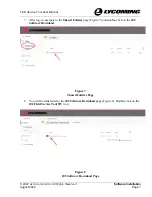
Page 17: ... Field Service Tool User Manual 7 After log in navigate to the Shared Folders page Figure 7 and double click on the iE2 Software Download Figure 7 Shared Folders Page 8 You will be transferred to the iE2 Software Download page Figure 8 Double click on the iE2 Field Service Tool SW icon Figure 8 iE2 Software Download Page ...

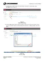
Page 18: ...nual 9 Check the box to the left of the iE2 Field Service Tool SW icon then click on the Download button Figure 9 Figure 9 File Download Page 10 Click the Save button from the pop up window at the bottom of the page Figure 10 and choose a file folder location for the download from the Save As dialog window then click Save Figure 10 File Save Page ...

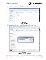
Page 19: ...Field Service Tool User Manual 11 From the file folder where the download was saved double click the iE2 Field Service Tool SW icon Figure 11 to open the Destination Directory Figure 11 Saved File Folder 12 Click the Setup button on the WinZip Self Extractor dialog box Figure 12 Figure 12 WinZip Self Extractor Dialog Box ...

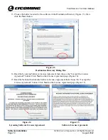
Page 20: ...Next button Figure 13 Destination Directory Dialog Box 14 Read the Lycoming Software License Agreement then choose the I accept the License Agreement button Click Next on the License Agreement page Figure 14 15 Read the National Instruments Software License Agreement then choose the I accept the License Agreement button Click Next on the License Agreement page Figure 15 Figure 14 Lycoming Software...

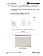
Page 21: ... separate folder for storing downloaded Active Fault Codes Separate folders for storing data from the Data Logger for LifeTime RunTime and TripTime A separate folder for storing downloaded Screen Shots A separate folder for storing Service History Faults A separate folder for storing TBO Fault History Figure 16 Folder on the Laptop Hard Drive 16 After the Installation Complete message is shown cli...

Page 22: ...TEO 540 C1A Engine Maintenance Manual Software Installation 2022 Avco Corporation All Rights Reserved Page 12 August 2022 Field Service Tool User Manual This page intentionally left blank ...

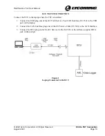
Page 23: ... ECU to the laptop where the FST is installed 1 Connect the USB plug end of the iE2 Field Service Tool CAN Interface ST 530 to the USB port on the laptop 2 Connect the CAN Interface plug end of the iE2 Service Cable ST 528 to the CAN Interface 3 Connect the RCA plug end of the iE2 Service Cable ST 528 to the airframe supplied RCA jack in the cockpit Figure 1 Laptop Connected to the ECU ...

Page 24: ...TEO 540 C1A Engine Maintenance Manual ECU to FST Connection 2022 Avco Corporation All Rights Reserved Page 14 August 2022 Field Service Tool User Manual This page intentionally left blank ...

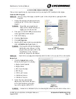
Page 25: ... Turn on the laptop 4 Click the Start button 5 Click All Programs 6 Find the FST Folder in the menu and double click on Field Service Tool Figure 1 NOTICE The program will open and display the Home screen Figure 2 If the program does not open refer to the Field Service Tool Software Problems chapter in this manual Figure 1 Field Service Tool Folder NOTICE Each Tab is an independent function and do...

Page 26: ...ables with damaged connectors 3 Attach the cable per the ECU to FST Connection Chapter in this manual 4 Start to FST program per the Start the FST Program 4 If the engine serial number displayed by the FST is not the same as the serial number on the engine data tag A Click the Edit Engine S N Figure 4 button on the Engine Serial Number panel B Enter the correct engine serial number in the New Seri...

Page 27: ...6 3 Click the Start button on the ECU Active Data screen Figure 6 to display active faults data from the ECU NOTICE If the Active Faults panel is blank there is no active fault data in the ECU Figure 6 ECU Broadcast Faults Tab 4 Click the Stop button Figure 7 to stop reading active data from the ECU NOTICE Must be streaming active data to record Figure 7 Start and Stop Record Buttons 5 Click the S...

Page 28: ... Service Tool User Manual Uploading Fault History 1 Open the FST program per the Start the FST Program procedure 2 Click on the Retrieve Clear Faults tab Figure 8 Figure 8 Retrieve Clear Faults Tab NOTICE The destination file pathway for each data category is associated with that data category on the Info Tab Figure 9 Figure 9 Info Tab ...

Page 29: ... down menu Figure 11 select one of the following options Reset TLO Time Clear Service History Faults Reset TPS Correction Factor Reset Ign Switch Cycle Count 2 Click the OK Button on the ECU Messages drop down menu to clear the selected faults from the ECU Figure 10 Retrieve DLU Data Figure 11 ECU Messages NOTICE The data from the Data logger unit will be logged in a folder in the FST folder on th...

Page 30: ... the data logger and the ECU and correct the problem If the problem persists contact Lycoming Figure 13 Data Logger Unit Not Detected 1 From the Retrieve DLU Data drop down menu Figure 14 select the following option Run Time Data Trip Time Data Life Time Data 2 Click the OK button to start to retrieve the selected data The Data Table will show streaming data from the ECU Figure 14 Retrieve DLU Dat...

Page 31: ...e data logged by the field service tool This feature can be used when the ECU is not connected Figure 15 1 Open the FST program per the Start the FST Program procedure NOTICE All tabs except Info are disabled when the FST is started with no hardware attached Figure 15 2 Click on the Graph Data button Figure 15 Figure 15 Open Data Folder Button 3 The program will open a separate Data Graph window F...

Page 32: ...button Figure 17 to open the file for path selection and select a runtime file 5 Right or Left click the button for the data you want to plot from the right hand column Figure 18 Figure 17 Data Graph Window Plot Visible 6 Click the Plot Visible button on the drop down menu Figure 17 NOTICE The Drop Down menu also has selections to personalize the graph Figure 18 Data Graph Window Plot ...

Page 33: ...ht or Left clicking the buttons for the data you want to plot from the right hand column As an example Figure 19 shows data plots for all six EGTs Figure 19 Data Graph Window Data Plots for all Six EGTs NOTICE Navigation buttons Figure 20 to move enlarge reduce and isolate sections of the graph are available to use by clicking on the icons in the lower left of the Data Graph Window Figure 20 Navig...

Page 34: ...e screen 1 Close the FST program by clicking on the Exit button at the bottom of the screen Figure 21 Figure 21 Exit Button Disconnect the ECU and FST 1 Turn power to the ECU OFF per instructions in the applicable aircraft manual 2 Disconnect the RCA plug of the ST 528 from the airframe supplied RCA jack in the cockpit 3 Disconnect the USB plug of the ST 530 adapter Figure 1 in the ECU TO FST CONN...

Page 35: ... laptop turned on and connected to the internet navigate to the Lycoming Engines Home Page www lycoming com 2 Open Lycoming s iE2 Portal Figure 1 and click on SHARE DATA Figure 1 Lycoming iE2 Software Portal 3 Enter your email name and company in the designated areas on the left hand side of the page Figure 2 4 Click on the icon for all the data files you want to share with Lycoming Technical Supp...

Page 36: ...EO 540 C1A Engine Maintenance Manual Sending Data to Lycoming Field Service 2022 Avco Corporation All Rights Reserved Page 26 August 2022 Field Service Tool User Manual This page intentionally left blank ...

Page 37: ...ervice Cable ST 528 CAN Adapter is not operating correctly Contact Lycoming for a replacement iE2 Field Service Tool CAN Interface ST 530 After opening the FST program the ECU Connection Status indicator in the lower left corner of the screen is not lit There is no communication between the laptop and the ECU Close the FST program per the Close the FST Program section in this chapter then start to...

Page 38: ...TEO 540 C1A Engine Maintenance Manual Field Service Tool Software Problems 2022 Avco Corporation All Rights Reserved Page 28 August 2022 Field Service Tool User Manual This page intentionally left blank ...

Reviews: