background image

Page 31

Connector Pinouts

L2Audio Port

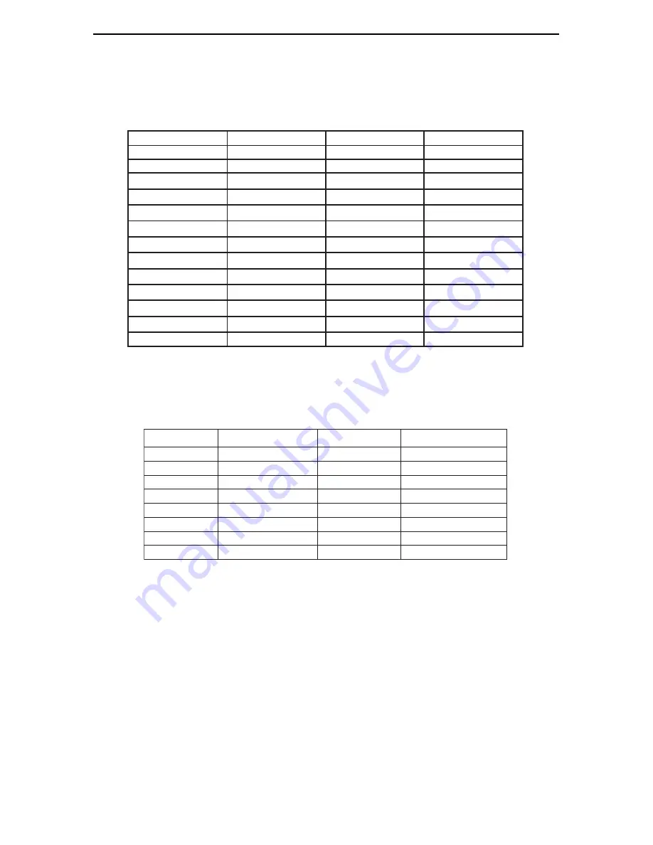
The L2Audio Port is a female 25-pin D-connector with the following connections:

n

i

P

l

a

n

g

i

S

n

i

P

l

a

n

g

i

S

1

t

o

H

4

T

U

O

4

1

d

l

o

C

4

T

U

O

2

d

n

G

4

T

U

O

5

1

t

o

H

4

N

I

3

d

l

o

C

4

N

I

6

1

d

n

G

4

N

I

4

t

o

H

3

T

U

O

7

1

d

l

o

C

3

T

U

O

5

d

n

G

3

T

U

O

8

1

t

o

H

3

N

I

6

d

l

o

C

3

N

I

9

1

d

n

G

3

N

I

7

t

o

H

2

T

U

O

0

2

d

l

o

C

2

T

U

O

8

d

n

G

2

T

U

O

1

2

t

o

H

2

N

I

9

d

l

o

C

2

N

I

2

2

d

n

G

2

N

I

0

1

t

o

H

1

T

U

O

3

2

d

l

o

C

1

T

U

O

1

1

d

n

G

1

T

U

O

4

2

t

o

H

1

N

I

2

1

d

l

o

C

1

N

I

5

2

d

n

G

1

N

I

3

1

e

n

o

n

L2Sync Port

The L2Sync Port is a female, high-density 15-pin D-connector with the following

connections:

n

i

P

l

a

n

g

i

S

n

i

P

l

a

n

g

i

S

1

9

t

o

H

t

u

O

l

a

ti

g

i

D

2

0

1

t

o

H

n

I

l

a

ti

g

i

D

3

+

n

I

C

T

L

1

1

4

+

n

I

c

n

y

S

2

1

5

t

o

H

n

I

l

a

ti

g

i

D

3

1

+

t

u

O

C

T

L

6

4

1

+

t

u

O

k

c

o

l

C

7

d

n

G

C

T

L

5

1

d

l

o

C

t

u

O

l

a

ti

g

i

D

8

d

n

G

k

c

o

l

C

Header Connectors

The LStream port is a 14 pin header shrouded in black plastic labeled J?.

The CLOCK IN and CLOCK OUT ports are two-pin headers shrouded in black plastic.

For both connectors, Pin 1 carries the clock signal and Pin 2 is a ground signal. Pin 1

is located on the left side of each connector when viewing the component side of the

board.

Appendix

Summary of Contents for LynxTWO

Page 1: ...Installation and Users Guide Lynx Studio Technology Inc 1048 Irvine Avenue 468 Newport Beach CA 92660 4602 www lynxstudio com support lynxstudio com ...

Page 2: ...Page 2 ...

Page 3: ...9 Using Your LynxTWO 10 The LynxTWO Mixer 10 Quick Audio Test 12 Mixer Reference 13 Mixer Menu 13 Adapter Window 13 Record Window 16 Play Window 16 Outputs Window 17 Working with Third Party Applications 18 Compatibility 18 LynxTWO Devices 18 Controlling Audio Bit Depth 18 Simultaneous Device and Multitrack Operation 19 Configuring Multiple LynxTWO s 20 Adapter ID s in a Multiple Card System 20 Se...

Page 4: ...ed the following in the LynxTWO shipping carton LynxTWO PCI Card in cushioned antistatic bag LynxTWO Audio Cable six foot cable with 8 XLR connectors LynxTWO Sync Cable two foot cable with 4 BNC connectors and six foot cable with 2 XLR connectors LynxTWO Installation and Users Guide Setup Disk for Windows Warranty Registration Card Optional Equipment The following equipment may be required dependi...

Page 5: ... with your LynxTWO 2 Use the Online Registration Wizard To start the wizard click on Start Programs Lynx Studio Technology Online Registration Wizard If you do not have an internet connection on the computer you installed your LynxTWO in simply copy the REGISTER EXE program from the C Program Files Lynx Studio Technology folder to a computer with an internet connection and run REGISTER EXE from th...

Page 6: ...ds 2 Touch a metal plate on your computer system to ground yourself and discharge any static electricity 3 Remove the cover from your computer system case You should refer to your computer system documentation for any special instructions on installing expansion cards and peripheral equipment 4 Find an empty PCI slot in your computer 5 Unscrew and remove the slot cover from your selected PCI slot ...

Page 7: ...ynxTWO from its static bag and gently insert it into the selected PCI slot Press it down firmly so that the contacts are securely seated in the slot 7 Secure the LynxTWO card with the screw removed from the slot cover 8 Replace the computer system case and plug in your computer 9 Connect the L2Audio and L2Sync cables to the LynxTWO See the External Connections section for more information Running ...

Page 8: ...he L2Sync cable Analog Audio The XLR connectors on theAudio Cable labeled IN 1 IN 2 IN 3 IN 4 OUT 1 OUT 2 OUT 3 and OUT 4 are used to connect balanced and unbalanced analog equipment to the analog inputs and outputs of the LynxTWO Make connections to professional consoles and other balanced equipment directly with these connectors Connect to balanced equipment with TRS jacks using XLR to TRS adapt...

Page 9: ... with external equipment The connectors support TTL or Composite Video level signals and should be connected with 75 ohm coaxial cable Connect the SYNC IN connector to the clock output or video output of an external device and select External as the Sample Clock Source in the LynxTWO mixer Adjust the clock Reference to match the incoming clock type CLOCK OUT is a word clock that tracks the sample ...

Page 10: ...After installation the LynxTWO Mixer icon will appear on the Windows task bar in the lower right corner of your screen By double clicking on this icon with your left mouse button the LynxTWO Mixer will launch Alternatively a single click with your right mouse button on this icon will open a menu that provides access to basic mixer controls and an Open Mixer selection that will also start the mixer...

Page 11: ...ock Source Reference must be set to External Word and the sample rate must be set to 44 1 kHz when a new file is being recorded in an application Failure to do so will result in files being recorded at the wrong sample rate Volume Faders and Signal Quality The faders in the LynxTWO Mixer perform digital attenuation on audio signals in the digital domain The attenuation is applied to the digitized ...

Page 12: ...check your connections 6 Disable input monitoring by again clicking on the Mute buttons on the Record 1 device After doing so the buttons should look like they are in the out or non depressed position 7 Start Sound Recorder by clicking Start Programs Accessories Multimedia Sound Recorder Position Sound Recorder on your screen so it be easily viewed along with the LynxTWO Mixer 8 In Sound Recorder ...

Page 13: ...rates Sample clock settings cannot be changed if any LynxTWO audio device is playing or recording Source Allows selection of the sample clock source from one of the following Internal Clock derived from the on board crystal oscillator Digital Clock signal from the DIGITAL IN connector on the L2Sync cable The Digital Format control must be correctly selected when selecting this clock source Externa...

Page 14: ...put sample rate will determine the actual rate of the Digital Output This mode is useful when sending audio to external equipment at a different rate than it was recorded Transmit Only Disables the Digital Input and the sample rate converter Digital Input Status Displays real time status of the digital input updated 4 times a second Digital In Rate Displays the measured rate of the incoming digita...

Page 15: ...s are calibrated for optimum fidelity Over time temperature changes inside your computer may cause the DC offset to drift slightly Because of this Lynx recommends recalibration 15 to 30 minutes after your computer has been turned on and whenever significant changes in room temperature occur Dither Type Provides selection of the type of dither used on all record channels The selection may be one of...

Page 16: ...ber channels in use on this device This is set by the audio application using each record device and is provided for reference purposes only Activity Indicators The names at the bottom of the Record and Play windows reflect the name of its associated wave device When a device is inactive its name is shown as blue text When a device is active currently open for play or record its name appears in re...

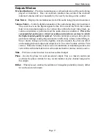
Page 17: ...position for critical recording and mixdown sessions in which the highest signal quality is required Volume control processing is done prior to peak meter readings causing the peak meters to reflect any volume control changes Since volume changes act on the digitally converted signals they have no effect on the analog full scale input and output levels This must be done with the Trim control When ...

Page 18: ...recording device and the output or playback device Multitrack applications provide multiple input and output device selection menus or windows Refer to the documentation included with your application to determine how to select audio devices With the LynxTWO properly installed in your computer the digital audio devices will be available to applications and their names will appear in their device s...

Page 19: ...LynxTWO operate completely independent in terms of whether they are in recording or playback modes and their associated audio files This implies that the devices can operate simultaneously and support the so called full duplex mode where for instance the LynxTWO Record 1 device is recording while the LynxTWO Play 1 device is playing Although the devices act independently when multiple devices are ...

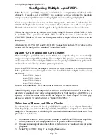
Page 20: ... and communicate with each LynxTWO when using the LynxTWO Mixer application and to select audio devices in third party applications In the LynxTWO Mixer the adapter that a user wishes to control is selected from the Mixer pull down menu In a system with four LynxTWO s the adapters will be listed as follows LynxTWO 1 Mixer LynxTWO 2 Mixer LynxTWO 3 Mixer LynxTWO 4 Mixer In each case the adapter ID ...

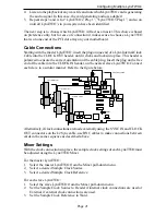
Page 21: ...e This header is polarized to ensure the correct orientation of the cable plug Insert the plug on the free end of the cable into the CLOCK IN header on the nearest slave LynxTWO Connect each slave in a similar manner Refer to the figure below Alternatively if clock connections are made externally using the SYNC IN and CLOCK OUT connectors on the L2Sync cable use BNC cables to make connections betw...

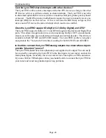
Page 22: ...the Plug and Play scan to detect new hardware which happens on each boot This is why Setup exe should generally be run before you install the LynxTWO into your computer To correct this follow the steps listed here 1 Load the device manager by clicking on Start Control Panel System Device Manager 2 There should be an entry called Other Devices listed about 3 4 down the page Click on the sign PCI Mu...

Page 23: ...er This requires the use of XLR to TRS adapters as described in the External Connections section I connect my microphone directly to the LynxTWO Analog Input connectors but the level is very low what is going on The LynxTWO Analog Input connectors should be connected line level devices only To record from a microphone first route the signal through a microphone pre amplifier or mixer and then into...

Page 24: ...AC 3 and DTS through its Digital In and Digital Out ports This allows an application to record an incoming Dolby or DTS encoded audio stream as well as play an encoded stream through an external decoder This ability is available for both S P DIF and AES EBU modes The LynxTWO is able to recognize and generate the Non Audio bit while recording for both S P DIF and AES EBU Is it safe to connect the L...

Page 25: ...mation about your problem please email us at support lynxstudio com In your email message include the following information The serial number of your LynxTWO Which operating system you are using The type of computer you are using The name of the application you are using A detailed description of the problem including any error messages you received We will provide a response in a timely manner Te...

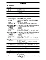
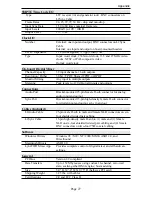
Page 26: ...A wtd Signal to Noise 114 dB A wtd Channel Crosstalk 120 dB 1 kHz signal 1dBFS THD N 104 dB 0 0006 1kHz signal 1dBFS 22 22 kHz BW Analog Out Performance measured in 24 bit mode with card installed in computer Frequency Response 20 20 kHz 0 05 dB at 44 1 kHz sample rate Dynamic Range 116 dB A wtd Signal to Noise 116 dB A wtd Channel Crosstalk 120 dB 1 kHz signal 1dBFS THD N 100dB 0 0010 1kHz signal...

Page 27: ...ts Connections Audio Port Bracket mounted 25 pin female D sub connector for analog audio input and output Sync Port Bracket mounted 15 pin high density female D sub connector for digital input and output sync in and out Cables Included L2Audio Cable 25 pin male D sub to male and female XLR connectors on six foot shielded twisted pair cabling L2Sync Cable 15 pin high density male D sub to 1 male an...

Page 28: ... signal wire and to the TRS tip XLR Pin 3 to the other signal wire and to the TRS ring Unbalanced Connections with Twisted Pair Cable The wiring method for unbalanced connections with XLR connectors to phone connectors tip and sleeve only using shielded twisted pair cable 2 wire shield is as follows XLR Pin 1 GND to cable shield with no connection on the other end XLR Pin 2 to signal wire and to t...

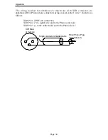
Page 29: ...dapt to unbalanced devices These cables are considerably more susceptible to interference and grounding problems than the two conductor cables shown above Two conductor cables should be used whenever possible The wiring method for unbalanced connections with XLR connectors to unbalanced phone connectors tip and sleeve only using coaxial cable 1 wire shield is as follows XLR Pin 1 GND no connection...

Page 30: ...ono phone connectors using coaxial cable 1 wire shield is as follows XLR Pin 1 GND no connection XLR Pin 2 to signal wire and to the Phono center pin XLR Pin 3 to the cable shield and to the Phono sleeve Appendix 1 2 3 XLR Male or Female Single conductor shielded cable RCA Phono Plug Unbalanced ...

Page 31: ... 5 2 d n G 1 N I 3 1 e n o n L2Sync Port The L2Sync Port is a female high density 15 pin D connector with the following connections n i P l a n g i S n i P l a n g i S 1 9 t o H t u O l a t i g i D 2 0 1 t o H n I l a t i g i D 3 n I C T L 1 1 4 n I c n y S 2 1 5 t o H n I l a t i g i D 3 1 t u O C T L 6 4 1 t u O k c o l C 7 d n G C T L 5 1 d l o C t u O l a t i g i D 8 d n G k c o l C Header Con...

Page 32: ...eception which can be determined by turning the equipment off and on the user is encouraged to try to correct the interference by one or more of the following measures Reorient or relocate the receiving antenna Increase the separation between the equipment and receiver Connect the equipment into an outlet on a circuit different from that to which the receiver is connected Consult the dealer or an ...

Page 33: ...ence to radio or television reception please refer to your user s manual for instructions on correcting the problem I the undersigned hereby declare that the equipment specified above conforms to the above requirements Newport Beach California June 15 2001 Robert Bauman Compliance Engineer EC DECLARATION OF CONFORMITY MANUFACTURERS NAME Lynx Studio Technology Inc MANUFACTURERADDRESS 1048 Irvine Av...

Page 34: ...ir Lynx reserves the right to change or improve design of the product at any time without prior notice This warranty does not cover claims for damage due to abuse neglect alteration or attempted repair by unauthorized personnel and is limited to failures arising during normal use that are due to defects in material or workmanship in the product ANYIMPLIED WARRANTIES INCLUDING IMPLIEDWARRANTIES OF ...

Page 35: ...Page 35 ...

Page 36: ......

Reviews: