CXA Series
User Manual
Lynx Pro Audio S.L
3
www.lynxproaudio.com
INTRODUCTION
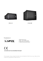
This manual describes the recommended installation procedure for the constant curvature line source
CXA-12 in combination with the subwoofer CXA-18S.
The CXA is intended as a flexible solution for both fixed installations and touring where wide coverage is
required from as few line array elements as possible.
Designed to be flown either horizontally or vertically, this line source system can be used as a single element
or a combination of a maximum of 4 cabinets in array configuration delivering a 72º coverage in the vertical
plane. Our custom HF Multidriver Waveguide system delivers 100H x 18V precise coverage for a multitude
of installations. Thanks to its careful construction it can also be installed for symmetrical HF dispersion.
The CXA Array models are self-powered (Class D) with switching power supply and 1400W of amplification
each. They are also controlled by the latest generation of Digital Signal Processing with a DSP integrated in
to each cabinet, optimizing all the system components and electronics, providing maximum system efficiency
and total protection.
CONTENTS
• SAFETY PRECAUTIONS
4
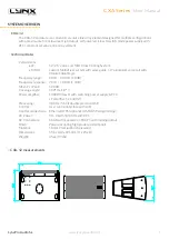
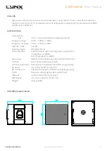
• SYSTEM OVERVIEW
CXA-12
5
CXA-18S 6
BACK PANEL
7
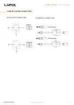
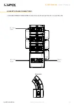
CONNECTORS AND CONNECTIONS
8
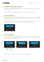
• CONFIGURING THE DIGITAL SIGNAL PROCESSOR
CONFIGURING THE DSP OPTIONS
12
CONFIGURATION PANEL
12
SELECT AND RUN PRESET
12
• ONLINE CONTROL SYSTEM
13
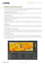
• RAINBOW 3D ACOUSTIC SIMULATION SOFTWARE
14
• HARDWARE AND ACCESSORIES
15
• APPLICATION EXAMPLES
16
• HOW TO USE THE FLYING FRAME ON CXA-12
18
• ASSEMBLY OF SV-CXA
20
• FITTING THE CXA-12 CABINETS TO THE FLYING FRAME
22
• FITTING THE CXA-18S CABINETS TO THE FLYING FRAME
23
• FITTING THE CXA-12 WITH CXA-18S CABINETS
24
• THE CEILING BRACKET
25
• CERTIFICATIONS AND GUARANTEE
26


