background image

Broken Spring(s) may cause the door to fall rapidly, 

causing SEVERE INJURY or DEATH.  

If possible 

only use the manual release when the door is closed, 

otherwise use caution when using the release while the 

door is open.

Moving chain could 

cause possible SERIOUS 

INJURY.  

DISCONNECT 

electric power to the 

operator BEFORE manually 

operating your door

IMPORTANT NOTE: Before your operator is installed, be sure the door has been properly aligned, balanced, and is working 

smoothly. 

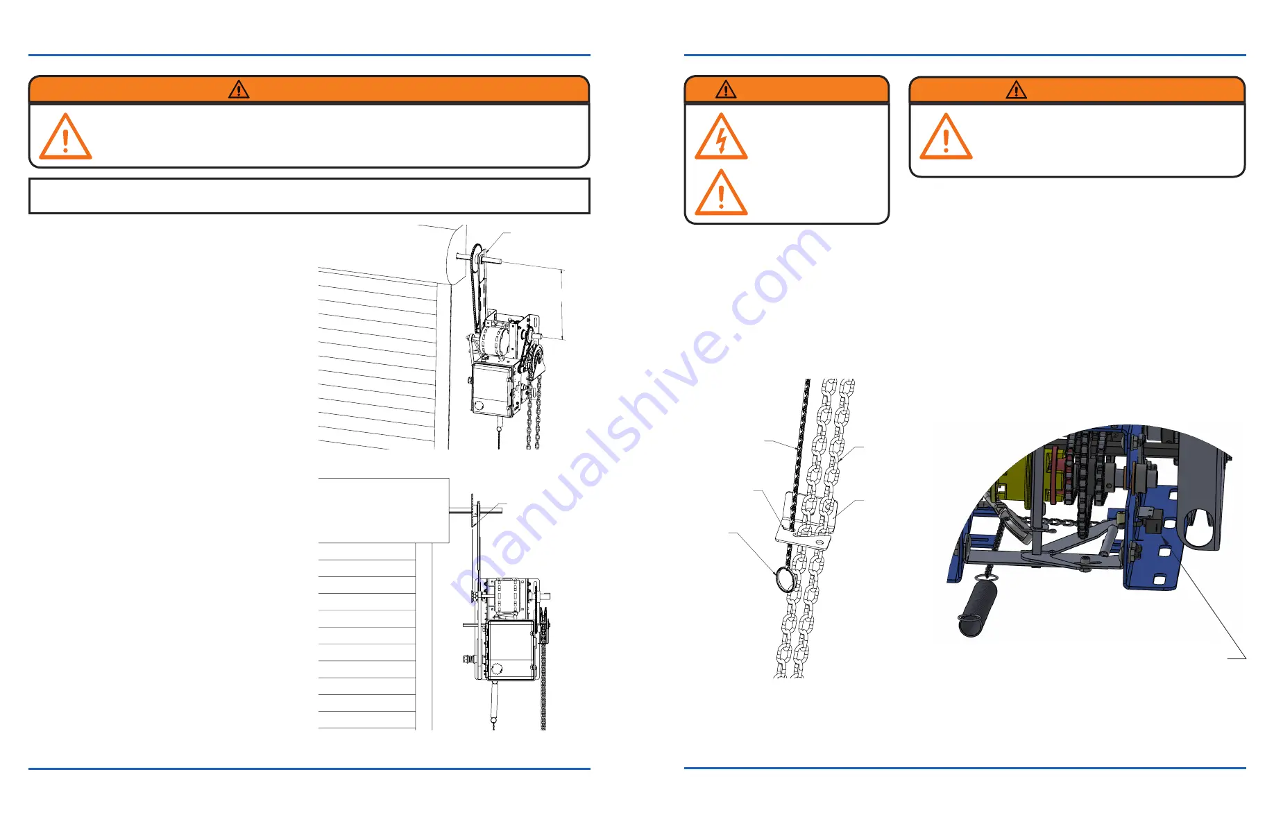
Sash Chain

Hand Chain

Sash Chain Lock

Wall Bracket

Pull Ring

INSTALLATION

1.  Wall Mount:


 A  The operator should generally be installed below 

the door shaft, and as close to the door as possible. 

The optimum distance between the door shaft and 

operator drive shaft is between 12-1/2” - 15-1/2” 

(Figure 2)

 B  Place the door sprocket on the door shaft. Do not 

insert the key at this time.

 C  Ensure the drive sprocket on the operator is on the 

appropriate side.

 D  Wrap the drive chain around the door sprocket and 

join the roller chains end together with master link. 

(NOTE: The chain may need to be made shorter 

depending on the operator mounting position)

 E  Raise the operator to approximate mounting position 

and position the chain over the operator drive 

sprocket.

 F  Raise or lower the operator until the chain is taut (not 

tight).  Make sure the operator output shaft is parallel 

to the door shaft and secure the operator in position.

 G  Align the door sprocket to the operator drive sprocket 

(Figure 3), insert the key, and secure with BOTH set 

screws.

2.  Install Hand Chain (Models MDJH and MDJBH 

only):

  Thread hand chain around hand chain wheel 

ensuring that it passes through both openings in the 

hand chain guide.  Remove enough links that so that 

the loop hangs approximately two feet above the floor. 

3.  Mount Manual Disconnect/Chain Keeper:

  Using 

suitable hardware, mount the manual disconnect 

directly beneath the operator approximately four 

(4) feet above the floor.  Install the sash chain on 

the spring that hangs from the operator and thread 

through the sach chain lock (Figure 4, page 5).  Pulling 

down on the sash chain pull ring, should disengage 

the motor from door assembly allowing for manual 

operation.

Optimum Distance

12 1/2" - 15 1/2"

Use Speader Bars

as Applicable

MDJ, MDJH, MDJB, MDJBH

MANUAL OPERATION

MDJ, MDJH, MDJB, MDJBH

FIGURE 3

Be sure door

sprocket is properly

aligned to drive

sprocket before

securing to the shaft

FIGURE 2

FIGURE 4

FIGURE 5

This operator has provisions for manually operating the door in case of emergency or power failure. 


1.  Pull the sash chain down until it is tight. Then lock it into the sash chain lock in the wall bracket (Figure 4).  This will 

disengage the motor.  It will also engage the hoist mechanism if present.

2.  Operate the door manually as desired.

3.  To return to electrical operation, release the sash chain from the lock (Figure 4).

WARNING

WARNING

WARNING

4

5

Moving parts on the operator could cause possible SERIOUS INJURY.  

Install the 

operator at least 8 feet above the floor to keep people away from the moving parts.

NOTE: When pulling the release mechanism, the manual disconnect switch circuit will open to stop motor movement from 

occuring (Figure 5).

Manual Disconnect Switch

Summary of Contents for MDJ

Page 1: ...M DUTY JACK SHAFT OPERATOR READ AND FOLLOW ALL INSTALLATION INSTRUCTIONS SAVE THESE INSTRUCTIONS This unit is intended for limited duty applications not to exceed 12 cycles of opening and closing per hour NOT FOR RESIDENTIAL USE 0MAGA0AA CDJ MANUAL 03 ...

Page 2: ...B2 Standard when powered C2 When photoeyes are blocked or not present LIMIT ADJUST Linear driven fully adjustable screw type cams Adjustable to 24 feet MDJ MDJH MDJB MDJBH MECHANICAL SAFETY PREPARATION MDJ MDJH MDJB MDJBH All MDJ MDJH MDJB and MDJBH operators have dual output shafts and may be mounted on either the right standard or the left side of the door Install the sprocket on the side desire...

Page 3: ...with BOTH set screws 2 Install Hand Chain Models MDJH and MDJBH only Thread hand chain around hand chain wheel ensuring that it passes through both openings in the hand chain guide Remove enough links that so that the loop hangs approximately two feet above the floor 3 Mount Manual Disconnect Chain Keeper Using suitable hardware mount the manual disconnect directly beneath the operator approximate...

Page 4: ...s Near and Opposite Side SENSING EDGES All types of sensing edges with an isolated normally open N O output are compatible with your operator This includes pneumatic and electric edges If your door does not have a bottom sensing edge and you wish to purchase one contact the supplier of your operator If not pre installed by the door manufacturer mount the sensing edge on the door according to the i...

Page 5: ...ROL WIRING MDJ MDJH MDJB MDJBH IMPORTANT NOTE Mount warning notice beside or below the push button station WARNING WARNING 8 MDJ MDJH MDJB MDJBH 9 PHOTO EYE INSTALLATION 1 Make sure that power is disconnected to the system prior to installing the photo eyes 2 Photo eyes need to be mounted inside the building They should be mounted on either side of the door and as close as possible to the door tra...

Page 6: ...ivating an OPEN button without the need to use the STOP button first for all 3 Modes To reduce the risk of serious injury or death follow these instructions carefully Read and follow ALL instructions Keep fingers and other body parts away from all moving parts of the door and gate operator system while it is being operated Keep the radio controls away from children Do not allow children to play wi...

Page 7: ...ic or manual is used Reversing devices are recommended for ALL installations CLUTCH ADJUSTMENT 1 Loosen the adjustment jam nuts until there is little tension on the clutch spring 2 Tighten the inner jam nut gradually until there is just enough tension to permit the operator to move the door smoothly but to allow the clutch to slip if the door is obstructed When the clutch is properly adjusted it s...

Page 8: ...RITY SENSITIVE NORMALLY OPEN SAFETY DEVICE OPTIONAL MOMENTARY SWITCH INTERLOCK WHEN NEEDED Rev 09 11 15 LX 900 Wiring Connections COAXIAL ANTENNA CONNECTION Stop and Com must be jumpered when a 3 Button Wall Station is not Present MDJ MDJH MDJB MDJBH 15 THE INFORMATION CONTAINED IN THIS DRAWING IS THE SOLE PROPERTY OF NAPOLEON LYNX ANY REPRODUCTION IN PART OR AS A WHOLE WITHOUT THE WRITTEN PERMISS...

Page 9: ...SHOP DRAWING MDJ MDJH MDJB MDJBH 16 14 1 15 4 18 0 0 750 10 0 1 50 TYP 0 50 0 406 18 0 5 5 6 5 5 0 TYP ...

Reviews: