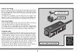
background image

1

2

Power Supply

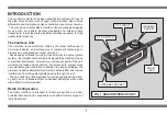
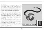
One or two headsets can be connected to the interface using the
locking connector sockets built in to the unit (fig 1). To simplify
operation, the interface draws its power directly from the self contained
Micro System Headset and does not require a separate battery. The
interface is switched on automatically, and is ready for use, once a
headset is connected. Some specialist Lynx headsets do not contain
an internal battery and can not be used with this interface unit.
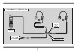
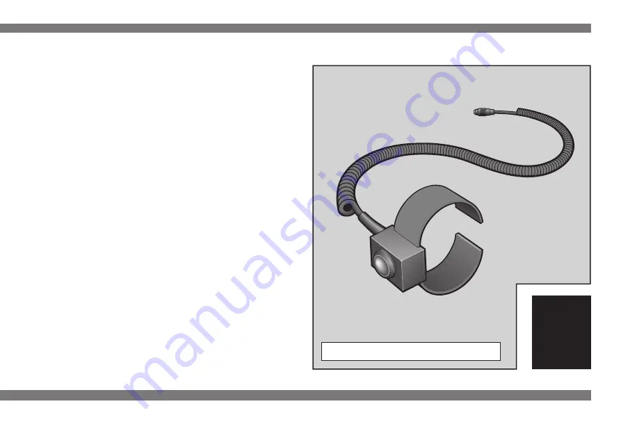
Push-To-Transmit

In order to provide the greatest flexibility of operation the interface
unit is fitted with a built-in 'Push-To-Transmit' (P.T.T.) switch, and a
P.T.T. input socket to allow a separate external switch to be connected.
  During the operation of a P.T.T. switch, one of the headset
microphones is opened, for radio transmission, and the microphone
of any additional headset is muted. In order to prevent unwanted
noise affecting the radio transmission only one headset is able to
transmit at a time.
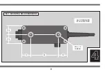
  The two headset connection sockets, on the interface unit, are
marked 'Pilot 1' and 'Pilot 2' in relation to the two P.T.T. switches. The
built-in switch controls radio transmissions from a headset connected
to the 'Pilot 1' socket. An external switch controls radio transmissions
from a headset connected to the 'Pilot 2' socket.
  A single headset can be used to transmit with either the built-in
switch or an external switch by selecting the appropriate headset
socket. Two headsets can be used with an external switch to allow
both headsets to transmit alternately.

FIG 2  OPTIONAL P.T.T. SWITCH

Summary of Contents for Micro System

Page 1: ...INSTRUCTIONS RADIO RADIO INTERF INTERFA ACE CE...

Page 2: ...been prepared to provide users of the Lynx Micro Communications System with the necessary information to enable safe and correct use Please read this booklet carefully and take time to familiariseyour...

Page 3: ...CONTENTS SECTION PAGE N 1 INTRODUCTION 1 2 SYSTEM CONFIGURATION 3 3 INSTALLATION 5 4 SPECIFICATION 7...

Page 4: ...proximity to engine ignition systems the interface electronics are designed to be virtually immune to electrical interference All electronic component parts of the unit including the leads and connec...

Page 5: ...ernal switch to be connected During the operation of a P T T switch one of the headset microphones is opened for radio transmission and the microphone of any additional headset is muted In order to pr...

Page 6: ...3 FIG 3 INTERFACE CONFIGURATION RADIO OPTIONAL P T T SWITCH BUILT IN P T T SWITCH INTERFACE UNIT...

Page 7: ...ing operation If necessary the headset leads can be extended by fitting an extension lead to the unit Depending on the application it may be desirable to fit either one or two headset extension leads...

Page 8: ...into the back of the unit for mounting purposes The threads accept M4 x 1 0 metric machine screws and allow the body of the interface to be screwed directly to a panel or bulkhead When mounting the u...

Page 9: ...ut do allow the unit to be easily fitted or removed The clips should be securely attached to the unit using the screws supplied fig 5 Cable Routing All cables connected to the interface should be care...

Page 10: ...available in two metre lengths and are fitted with one male connector and one female connector Radio Interference The main cause of radio interference can usually be attributed to the aircraft engine...

Page 11: ...4 8 FIG 6 MOUNTING HOLE DIMENSIONS 17 5 17 5 18 18 55 M4 x 1 0 THREAD ALL DIMENSIONS IN MILLIMETRES...

Reviews: