
2
4
SYSTEM CONFIGURATION
The Lynx Micro System concept is intended to simplify considerably
the configuration and operation of radio interface equipment within
the open cockpit environment.
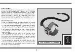
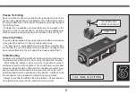
Solo Operation
For solo applications a single headset may be connected to either
headset socket on the unit depending on which P.T.T. switch is to be
used. If required the headset lead may be extended, using an optional
extension lead, to allow the unit to be conveniently located.
It is important to remember that the P.T.T. switch built into the unit
controls a headset connected to the 'Pilot 1' socket, and an external
P.T.T. switch controls a headset in the 'Pilot 2' socket. Always take
care when connecting a headset to ensure that the correct socket is
selected in relation to the required P.T.T. switch.
The headset connection to the unit should be bayonet locked, and
correct operation of the equipment should always be established, by
a radio check, before flight.
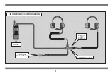
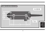
Dual Operation
For intercom and radio use, two headsets may be connected to the
unit with the option of an external P.T.T. switch. It is important to note
that the individual headsets must be correctly fitted to the unit in
relation to the relevant P.T.T. switch.
An external P.T.T. switch should be located in the aircraft in relation
to the relevant headset to avoid confusion during operation. If
necessary the headset leads can be extended by fitting an extension
lead to the unit. Depending on the application, it may be desirable to
fit either one or two headset extension leads to allow the unit to be
conveniently located.
Correct operation of the equipment should be established by a radio
check before flight, and again always make sure that the bayonet-
locks, on all of the connections to the unit, are properly engaged.
Radio Connection
The interface unit is normally fitted with a standard radio connector
which will connect directly to most available transceivers. The interface
electronics, however, are always configured to work with the specific
make and model of radio specified when ordering the unit.
Before using an interface with a radio, it is important to establish that
the unit is correctly configured, as connecting and using an interface
which does not match the radio may damage the unit or the radio.
Hand-portable radios must be powered from their own battery pack,
or an external power source, when used with the interface unit.
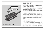
Antenna Connection
The antenna connected to a radio greatly affects the performance of
the radio, both during reception and transmission.
While it is possible to operate a hand-portable radio
in an aircraft using the short helical antenna, this
practice is not recommended. The fitting of a 1/4-
wave whip antenna to the aircraft effectively
increases the power of a radio, in comparison to
the helical antenna, and allows transmission and
reception over a much greater range.