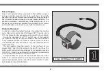
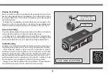
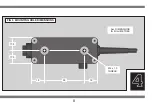
background image

3

6

Plastic Tie  Fitting

As an alternative to panel mounting it is also possible to fix the unit in
position using plastic ties and tie-saddles. This method of mounting
is useful to attach the unit to tubular structures and avoids the need
to drill fixing holes.
  Suitable ties, tie-saddles and screw fasteners are supplied in the
fixing kit. In order to use the ties for mounting, the tie-saddles must
first be securely screwed in position on the back of the unit (fig 4).
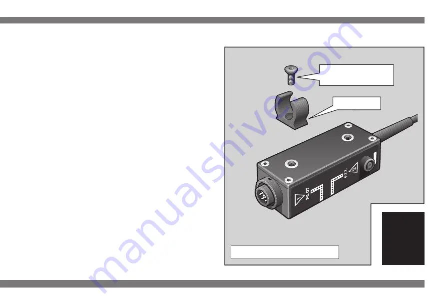
Tube Clip Fitting

The unit is also supplied with two tube clips, which offer an alternative
to the plastic tie method, for fixing to tubular structures.
  The tube clips are only suitable for use with 25mm diameter tube
but do allow the unit to be easily fitted or removed. The clips should
be securely attached to the unit using the screws supplied (fig 5).
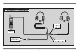
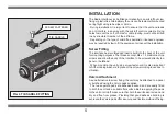
Cable Routing

All cables connected to the interface should be carefully routed around
the airframe and attached in position using the cable ties supplied.
  Avoid fitting the cables in close proximity to possible sources of
interference such as strobe lights or the aircraft antenna. Headset
extension leads should be fitted with the headset connecter in an
easily-accessible location next to the relevant seat. The external P.T.T.
switch and lead must be positioned in the aircraft, in relation to its
active headset, to avoid possible confusion during operation.
  Always check after installation that the interface unit and leads do
not interfere in any way with the operation of the aircraft.

COUNTERSUNK

SCREW FASTENER

FIG 5  TUBE CLIP FITTING

TUBE CLIP

Summary of Contents for Micro System

Page 1: ...INSTRUCTIONS RADIO RADIO INTERF INTERFA ACE CE...

Page 2: ...been prepared to provide users of the Lynx Micro Communications System with the necessary information to enable safe and correct use Please read this booklet carefully and take time to familiariseyour...

Page 3: ...CONTENTS SECTION PAGE N 1 INTRODUCTION 1 2 SYSTEM CONFIGURATION 3 3 INSTALLATION 5 4 SPECIFICATION 7...

Page 4: ...proximity to engine ignition systems the interface electronics are designed to be virtually immune to electrical interference All electronic component parts of the unit including the leads and connec...

Page 5: ...ernal switch to be connected During the operation of a P T T switch one of the headset microphones is opened for radio transmission and the microphone of any additional headset is muted In order to pr...

Page 6: ...3 FIG 3 INTERFACE CONFIGURATION RADIO OPTIONAL P T T SWITCH BUILT IN P T T SWITCH INTERFACE UNIT...

Page 7: ...ing operation If necessary the headset leads can be extended by fitting an extension lead to the unit Depending on the application it may be desirable to fit either one or two headset extension leads...

Page 8: ...into the back of the unit for mounting purposes The threads accept M4 x 1 0 metric machine screws and allow the body of the interface to be screwed directly to a panel or bulkhead When mounting the u...

Page 9: ...ut do allow the unit to be easily fitted or removed The clips should be securely attached to the unit using the screws supplied fig 5 Cable Routing All cables connected to the interface should be care...

Page 10: ...available in two metre lengths and are fitted with one male connector and one female connector Radio Interference The main cause of radio interference can usually be attributed to the aircraft engine...

Page 11: ...4 8 FIG 6 MOUNTING HOLE DIMENSIONS 17 5 17 5 18 18 55 M4 x 1 0 THREAD ALL DIMENSIONS IN MILLIMETRES...

Reviews: