


Lynx NGT-9000
Installation Manual
3.10 INSTALLATION CHECKOUT
This procedure validates the installation, calibration, and configuration setup of the Lynx NGT-9000s and
secondary equipment. Installers are advised to read through the entire procedure and ensure all the
necessary tool, equipment, and data are available before performing the checkout.
Take the following into consideration prior to installation.
•
Perform the installation checkout procedure with aircraft on ground.
•
Perform only those checks that are applicable to the installation.
•
To conserve aircraft battery power, it is recommended that the aircraft be connected to an external
aircraft power source during installation and checkout.
•
An IFR-6000 (or equivalent) Ramp Test Set is required with the UAT option installed. These checks
assume familiarity with the set up and operation of the ramp test set.
•
All test equipment shall be calibrated in accordance with the manufacturer’s recommendations.
•
If the ADS-B Out Fail lamp is installed it flashes ON/OFF while the unit is starting and GPS is
initializing (acquiring signal).
•
It is normal for the TIS-B Out Of Coverage lamp to be ON during checkout if there is not a ground
station or signal within range.
3.10.1 Functional Checks
Use the following procedure to check that the Lynx NGT-9000s (the unit) and secondary equipment is
operating properly.
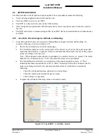
3.10.1.1 WiFi Check
This check required only if the WiFi option is installed and requires a WiFi accessory connected to the
wiring harness. The PED requires an approved APP be installed.
NOTE
This check requires a valid signal (ADS-B In with TIS-B and/or FIS-B service).
It is also possible to use an IFR-6000 set up and simulate the information.
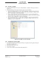
1.
The PED, unit WiFi interface, and WiFi Dongle must be configured.
2.
Verify that the PED is receiving data from the unit and that traffic and weather (if available) data is
being displayed.
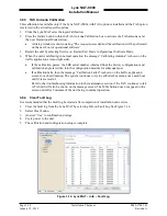
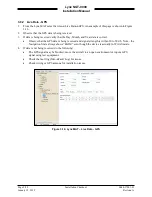
3.10.1.2 System Status Check
Use the following procedure to check equipment interfaces and operation of the unit.
1.
Apply power to the unit.
•
Initialization and self-tests begin.
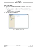
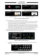
2.
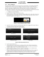
The splash screen is displayed in less than 5 seconds. See Figure 3-19.
•
The company name/Logo is shown on the left side and the product name on the right.
0040-17001-01
Installation Checkout
Page 3-23
Revision A
January 15, 2015