Lynx NGT-9000
Installation Manual
2.
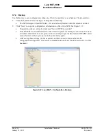
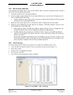
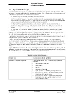
If heading is not being input to the Lynx NGT-9000, then select Ground Test and enter a Simulated
Own Direction (0 – 359 deg.). The own direction is the current true heading of the aircraft A unit
with a heading input can ignore this step.
NOTE
When entering heading information into the IFR-6000 UUT HDG entry
field make sure to enter either the same simulated heading as was entered
into the Lynx MAT own direction field or the actual aircraft heading (true
heading) as appropriate.
3.
Click on the Restart Unit button.
4.
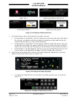
The unit starts up in normal operation, but an amber “Ground Test” message is shown below the
options button on the right side of the display.
•
Cycling power at anytime takes the unit out of Ground Test Mode. (Note: Ground Test Mode is
automatically, without cycling power, exited if aircraft flight is detected).)
5.
Continue with the checkout procedures below.
3.10.2.2 Altitude Check
1.
Perform the altitude check per 14 CFR Part 91.411 and 14 CFR Part 43 Appendix E & F.
2.
Verify that the displayed altitudes of the unit and the primary display (PFD) or equivalent instrument
are within the required range shown below (per the installation):
•
Gilham Code altitude source the range is +/- 100 ft.
•
Other altitude source the range is +/- 25 ft.
3.10.2.3 Transponder Output Check
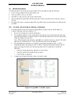
Verify that the Transponder test performed by the test set is successful and that the test set is receiving the
correct transponder information (i.e. Mode S Identifier, Flight ID, etc). This check requires an IFR-6000
(or equivalent) Ramp Test Set and the Lynx MAT.
1.
Set ground test (in air) mode (see para. 3.10.2.1) on NGT-9000 using Lynx MAT.
2.
Enter the XPDR setup page of the IFR-6000 and ensure that the antenna/cable loss setup is correct.
3.
Run the Generic Mode S test and verify “PASS” (in air).
•
The IFR-6000 must be located in the nominal position or the power/frequency test may fail.
4.
Set NGT-9000 normal mode (on ground) using the Lynx MAT (restart unit in operational software
mode) or cycling power to the NGT-9000.
5.
Run Generic Mode S test using the IFR-6000. Verify that a “PASS” is shown at the top of the IFR-
6000 on-ground results page.
•
It may be necessary to manually enter the aircraft’s ICAO code in the XPDR setup page of the
IFR-6000 when the NGT-9000 is in normal mode (on ground).
3.10.2.4 ADS-B Out Check
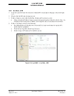
Before performing this check ensure that the GPS position on the NGT-9000 is acquired. If installed the
ADS-B Out Fail lamp is OFF, and the external display/PED is ON (if installed).
1.
From the ADS-B/GICB/UAT screen on the IFR-6000, select ADS-B MON ADS-B.
2.
Verify that the ADS-B Out test performed by the test set is successful.
3.
Ensure correct AA (Aircraft Address) in HEX and OCTAL.
0040-17001-01
Installation Checkout
Page 3-29
Revision A
January 15, 2015


