Lynx NGT-9000s
Installation Manual
4.6 RETURN TO SERVICE
Use this section to validate the return to service of the Lynx NGT-9000s and system components.
4.6.1 Lynx NGT-9000s
Use this procedure to remove and replace all models of the panel mount NGT-9000s. The instructions
herein are generic in scope. The best established methods, techniques and practices should be used where
no specific procedure is given.
1.
Removal Procedure
a.
Locate the Panel Retainer access on the bottom left of the bezel.
b.
Rotate the Panel Retainer CCW using 3/32 Allen Hex Socket Screw Driver. Rotate Panel
Retainer, approximately 40 turns, until it stops. Do not exceed 5.0 inch-pounds of torque.
c.
Pull the unit from panel separating the main connector and antenna connections.
2.
Installation Procedure
a.
Use 3/32 Allen Hex Socket Screw Driver to rotate the Panel Retainer CCW to avoid
interference with the bottom edge of the panel.
b.
Insert the unit in panel allowing the alignment guides to settle the unit into place.
c.
Press the sides of the unit until the back side of the bezel is against the panel.
d.
Rotate the Panel Retainer CW (approximately 40 turns) to lock the unit in place. The Panel
Retainer torque limit is 5.0 inch-pounds.
4.6.1.1 Functional Check Procedure
1.
Cycle power to the unit and system components.
2.
The Lynx NGT-9000s contain a GPS receiver that requires a full functional check (paragraph 3.10,
Installation Checkout) be performed to verify unit is functioning correctly.
3.
Models of NGT-9000 with the TAS function must perform the TAS Antenna Calibration (installation
checkout paragraph 3.10.2.8) prior to doing a functional check.
4.
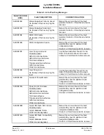
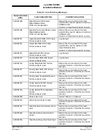
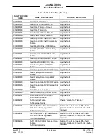
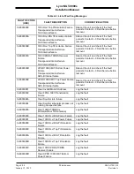
Refer to the fault isolation section if errors are detected.
0040-17001-01
Maintenance
Page 4-29
Revision A
January 15, 2015

