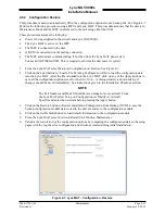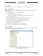
Lynx NGT-9000s
Installation Manual
4.6.2 Detachable Configuration Module
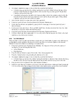
Use this procedure to remove and replace the DCM. The instructions herein are generic in scope. The best
established methods, techniques and practices should be used where no specific procedure is given.
NOTE
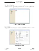
Before removal (and if possible) the configuration data should be saved.
Refer to the Lynx MAT Backup instructions located in the installation
checkout section.
1.
Removal Procedure
a.
Locate the Panel Retainer access on the bottom left of the Lynx NGT-9000s bezel.
b.
Rotate the Panel Retainer CCW using 3/32 Allen Hex Socket Screw Driver.
c.
Pull the unit from panel separating the main connector and antenna connections.
d.
Remove 6 screws securing panel rack and remove panel.
e.
Remove 4 screws securing rear plate to panel rack.
f.
Remove 2 screws securing P1 mating connector and nut plate. Remove screw securing ground
strap to rear plate.
g.
From the wire bundle remove tie wraps securing overbraid.
h.
Slide overbraid to expose configuration module.
i.
Remove configuration module contacts from the P1 mating connector.
2.
Installation Procedure
a.
Insert contacts of new configuration module into P1 mating connector. Refer to Installation
Guidelines for the Configuration Module in the installation section for details on the
configuration module and configuration module electrical interface.
b.
Slide overbraid back into position, and use a new tie wraps to secure overbraid.
c.
Secure P1 mating connector to rear plate using nut plate and 2 screws.
d.
Secure cable ground strap to rear plate using 1 screw.
e.
Secure rear plate to panel rack using 4 screws.
f.
Insert panel in installation location and secure panel using 6 screws.
g.
Secure panel rack using 6 screws.
h.
On the Lynx NGT-9000s use 3/32 Allen Hex Socket Screw Driver to rotate the panel retainer
counterclockwise to avoid interference with the bottom edge of the panel.
i.
Insert the Lynx NGT-9000s in panel allowing the alignment guides to settle the unit into place.
j.
Press the sides of the unit until the back side of the bezel is against the panel.
k.
Rotate the panel retainer clockwise to lock the Lynx NGT-9000s in place. The Panel Retainer
torque limit is 5.0 inch-pounds.
3.
Functional Check Procedure
a.
Cycle power to the Lynx NGT-9000s and system components.
b.
Ensure no failure messages are annunciated on the controller/display/PED and fail lamp is
extinguished after GPS has acquired a signal.
c.
Use the installation checkout section to perform the select configuration options procedure or
use the maintenance sections configuration restore is the original configuration (.bin) file can be
retrieved from the original installer of the configuration module.
d.
Perform the checkout procedure provided in the installation checkout to verify unit is
functioning correctly.
•
Refer to the fault isolation section if errors are detected.
Page 4-30
Maintenance
0040-17001-01
January 15, 2015
Revision A

