Lynx NGT-9000s
Installation Manual
1.3 EQUIPMENT DESCRIPTIONS
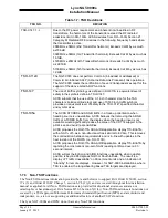
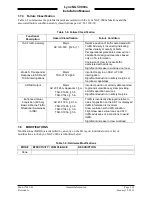
The Lynx MultiLink Surveillance System includes a Detachable Configuration Module (DCM). A panel
mounted rack is required for installation. Additional 3
rd
party components are necessary to complete the
installation. Refer to paragraph 1.5 for component requirements and installation considerations. Details on
these components are provided in paragraph 1.11.
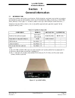
The unit has a bezel containing a multifunction touch screen that is designed to fit into a MARK width
panel. LED backlighting is controlled by either the auto-dimming functionality provided by the ambient
light sensor or using the pilot adjustable brightness control. The unit is equipped with a main sub-D
connector (J1) and RF connectors. A USB port is available to establish communication between the unit
and a maintenance computer for installation and maintenance activities.
The multifunction touch screen has full operational control providing the means to select screen views
and interface with transponder, traffic, and weather information. The following information is available
for display and control:
•
Flight ID or aircraft Tail Number
•
Transponder and Traffic Mode of Operation
•
ADS-B Status
•
VFR Select and Squawk Code Input
•
IDENT
•
Traffic (graphic and textual)
•
Weather (graphic and textual)
•
TAS Mode (model specific)
1.3.1 Model Options
The Diversity option offers enhanced traffic awareness receiving data via 1090MHz using the ADS-B
service.
The Traffic Awareness System (TAS) option provides additional traffic awareness when ADS-B
equipped aircraft are not in the area providing Traffic Alert (TA) warnings to the flight crew. See
paragraph 1.2.6 for TAS functionality.
The Diversity and TAS options require an unlock codes that are entered using the Lynx MAT.
Models with Diversity require the installation of an additional L-Band antenna. The TAS option requires
the installation of a directional antenna.
1.3.2 Detachable Configuration Module (DCM)
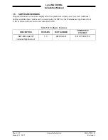
The DCM part number 9230-17003-01 is part of the Lynx NGT-9000s and is used for the storage of
configuration data. The DCM is permanently installed with the wire harness and interfaces to the unit via
a 4 wire interface from the DCM.
The configuration settings are stored in the unit’s non-volatile memory and are entered via commands
sent over the maintenance interface to configure such items as; input / output interface options, aircraft
specific options (including TAS and Diversity), and installation calibration parameters.
When the configuration data is set, Lynx NGT-9000s units may be swapped and the configuration
remains with the aircraft.
Page 1-6
General Information
0040-17001-01
January 15, 2015
Revision A

