


Lynx NGT-9000s
Installation Manual
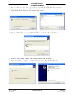
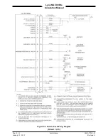
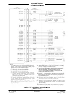
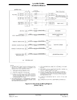
2.3 INSTALLATION PROCEDURES
1.
The installer must take the following into consideration prior to installation. Specific procedures for
installation of the Lynx NGT-9000s, Data Configuration Module, Mounting Rack, and Directional
Antenna (for TAS option) are detailed in their respective paragraphs below.
•
The installer must obtain installation approval (i.e. Supplemental Type Certification).
•
Follow the acceptable avionics installation practices in FAA Advisory Circulars AC 43.13-1B
and AC 43.13-2B or later revision of these documents.
•
It is the responsibility of the equipment installer to determine that the required aircraft viewing
envelope is within the specified display viewing envelope(s). Refer to paragraph 2.3.1.
•
Bonding impedance between aircraft ground and the unit chassis must be less than 2.5
milliohms.
•
It is recommended that the aircraft battery be disconnected before performing installation
procedure.
•
Installers are responsible for obtaining installation hardware (i.e. screws, supporting plates, etc)
beyond those parts that come with the installation kits.
•
It is recommended that one of the following Installation Kits be used for the installation of the
unit. Refer to the General Information section for details.
o
Rack Assembly with Straight Coax Connector P/N 9060-17000-01
o
Rack Assembly with Right Angle Coax Connector P/N 9060-17000-02
•
All antenna cables should be clearly marked to prevent inadvertent installation into the wrong
connector position.
•
Tighten all screws to snug (i.e. only such torque that can be applied by hand) unless specific
torque instructions are given.
•
After installation, refer to the Installation Checkout section for calibration, calibration, power-
up and ground testing procedures.
2.
Electrical equipment chassis, shield/ground terminations, antennas, supporting brackets, and racks
must be electrically bonded to the aircraft's main structure (metallic aircraft) or instrument panel
(composite aircraft). Compliance of the electrical bonding should be verified by inspection using a
calibrated milliohm meter. An equivalent OEM procedure may also be substituted.
•
The electrical bond should achieve direct current (DC) resistance less than or equal to 2.5
milliohms to structure local to where the equipment is mounted for metallic aircraft or tube and
fabric aircraft.
•
The electrical bond should achieve direct current (DC) resistance less than or equal to 5.0
milliohms to the instrument panel for composite aircraft.
The antenna ground plane must be electrically bonded to the antenna baseplate. Do not remove paint
on outer skin of aircraft under the footprint of the antenna baseplate unless necessary to meet
bonding requirements. Refer to antenna manufacturer's installation instructions.
Page 2-2
Installation
0040-17001-01
January 15, 2015
Revision A


