

Lynx NGT-9000s
Installation Manual
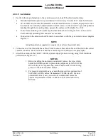
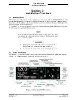
2.3.2.4 Coax Connector Assembly
The number of antenna cables required for installation is based on the model of Lynx NGT-9000s. The
basic model has a GPS and omnidirectional (bottom mounted L-Band) antenna connection. Models with
Diversity only have a secondary top mounted L-Band antenna connection. Models with TAS have three
directional antenna connections.
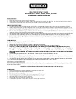
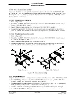
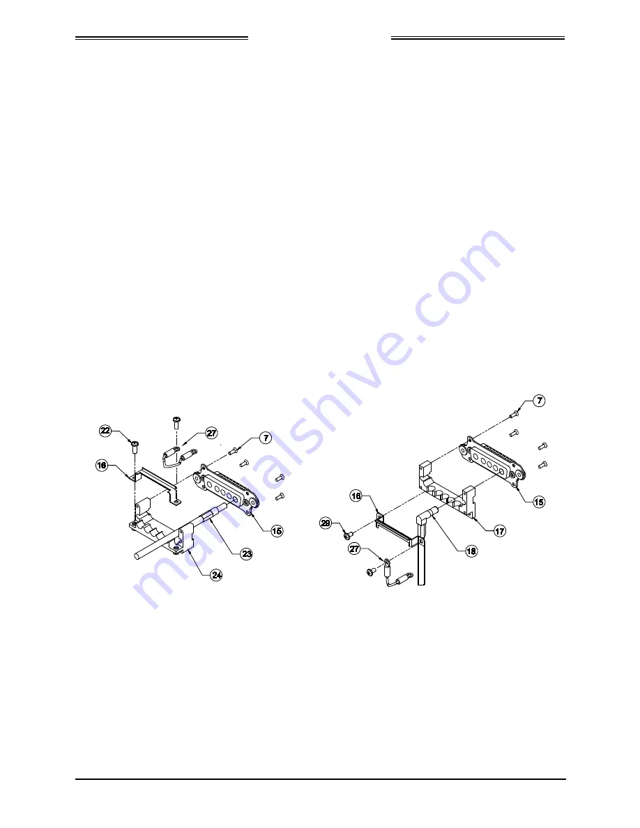
2.3.2.4.1 Straight Coax Connector
1.
Refer to Figure 2-11.
2.
Secure Backshell P/N 9000-17106-01 (item 24) to Connector P/N 9080-17007-01 (item 15) using 4
Screws P/N 2000-10085-01 (item 7).
3.
Insert Cables into the appropriate slots of Connector P/N 9080-17007-01 (item 15).
4.
Secure 1 Spring Clip P/N 90001963-001 (item 16) and 1 Cable Ground Strap P/N 9020-17002-01
(item 27) to Backshell P/N 9000-17106-01 (item 24) using 2 Screws P/N 2000-10087-01 (item 22).
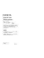
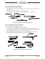
2.3.2.4.2 Right Angle Coax Connector
1.
Refer to Figure 2-11.
2.
Secure Backshell P/N 9000-17105-01 (item 17) to Connector P/N 9080-17007-01 (item 15) using 4
screws P/N 2000-10085-01 (item 7).
3.
Insert Cables into the appropriate slots of Connector (item 15).
4.
Secure 1 Spring Clip P/N 90001963-001 (item 16) and 1 Cable Ground Strap P/N 9020-17002-01
(item 27) to Backshell (item 17) using 2 Screws P/N 101-10114-011 (item 29).
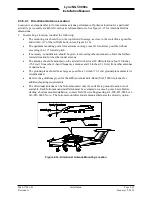
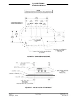
Straight Connector
Right Angle Connector
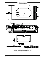
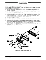
Figure 2-11: Connector Assembly
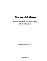
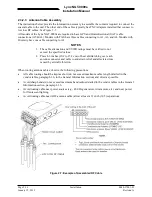
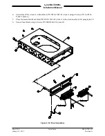
2.3.3 Panel Installation
This procedure assumes that the mating connector and Antenna Cables are assembled. Refer to Figure 2-12.
1.
Secure P1 Mating Connector to Rear Plate P/N 9000-17025-02 (item 2) using Nut Plate P/N 9000-
17034-01 (item 6) and 2 Screws P/N NAS514-P-440-7 (item 3).
2.
Secure assembled Antenna Connector to Rear Plate P/N 9000-17025-02 (item 2) using Nut Plate P/N
9000-17036-01 (item 5) and 2 Screws P/N NAS514-P-440-7 (item 3).
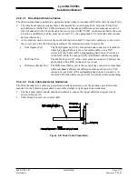
3.
Attach end of Cable Ground Straps P/N 9020-17002-01 (item 27) to Rear Plate (item 2) using 2
screws P/N 2000-10087-01 (item 22).
0040-17001-01
Installation
Page 2-19
Revision A
January 15, 2015