

Lynx NGT-9000s
Installation Manual
2.3.5.1 GPS Antenna
The GPS antenna performance is critical to the performance of the Lynx NGT-9000s. The antenna must
meet the minimum performance requirements for the Lynx NGT-9000s.
•
The recommended antenna is a DO-301 compliant antenna meeting the requirements of TSO-C190.
For installations where the aircraft has an existing antenna complying with DO-228 (TSO-C144a),
the unit may be installed utilizing this antenna, as per DO-229D Note 1, Section 2.1.1.10. Use the
antenna location information below to verify an existing antenna location is acceptable for use.
•
The performance of the unit is affected by the gain, noise figure, impedance, and frequency
selectivity characteristics of the antenna. The unit should be used only with the recommended
antenna and cable. Use of other antennas or cables may not meet all the performance characteristics
specified in DO-229D.
•
The cable including connectors, loss should not exceed 10dB.
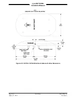
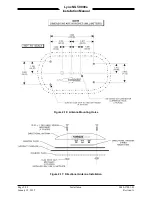
2.3.5.1.1 GPS Antenna Location
The following guidance provides information to aid the installer in determining the best location is
selected for the installation of the GPS Antenna.
The installation guidelines presented here meet the intent of AC 20-138C Chapter 12, Section 12-1.
NOTE
Not all the listed installation guidelines may be possible on all aircraft.
The guidelines are listed in order of importance. The chances of optimal
signal strength are decreased if the guidelines are not followed.
1.
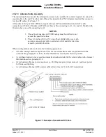
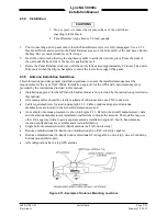
The antenna must be located on the top of the aircraft and should be mounted in a location to
minimize the effects of airframe shadowing during typical maneuvers. Typically mounting farther
away from the tail section reduces signal blockage seen by the antenna.
2.
Mount the antenna as close to level as possible with respect to the normal cruise flight attitude of the
aircraft. If the normal flight attitude is not known, substitute with the waterline, which is typically
referenced as level while performing a weight and balance check. A shim may be used to level the
antenna.
3.
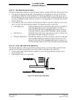
The antenna should be mounted no closer than 3 feet from any VHF COM antenna or any other
antenna, which may emit harmonic interference at the L1 frequency of 1575.42 MHz. An aircraft
EMI check can verify the degradation of GPS in the presence of interference signals.
•
If an EMI check reveals unacceptable interference, either insert a GPS notch filter in line with
the offending VHF COM or select a different GPS Antenna location.
4.
To maintain a constant gain pattern and limit degradation by the windscreen, avoid mounting the
antenna closer than 3 inches from the windscreen.
5.
It is permissible to temporarily locate the GPS Antenna with a coaxial cable connected to the unit
and check the GPS performance as described in the installation checkout section. Permanently mount
the antenna once a suitable location has been verified.
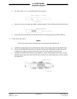
6.
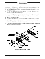
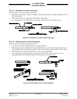
Once the antenna mounting position has been established, route the coaxial cable from the antenna to
the Lynx NGT-9000s. Proper selection of coaxial cable and assembly of connectors is critical to GPS
signal performance.
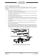
7.
For installations on rotorcraft, ensure that the rotor blades do not interfere with the GPS received
signal. This problem has been experienced in some rotorcraft and varies with rotation rate.
Page 2-22
Installation
0040-17001-01
January 15, 2015
Revision A