Lynx NGT-9000s
Installation Manual
2.3.5.1.2 GPS Antenna Installation
Refer to the aircraft manufacturer's data and the antenna manufacturer's installation instructions to mount
the antenna. The installer may use other FAA approved data to gain a separate antenna installation
approval.
1.
Electrical Bonding Requirements:
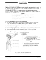
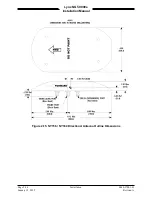
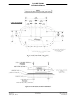
The GPS/WAAS antenna requires a minimum ground plane radius of 7.5 inches around the
perimeter of the antenna. For metal aircraft, the surrounding metal skin on which the antenna is
mounted supplies the ground plane. For non-metal aircraft, the ground plane can be composed of
heavy duty aluminum foil tape, such as 3M PIN 438 or other adhesive backed dead soft aluminum
foil minimum 0.012 inches thick. It should be noted that if the antenna is struck by lightning, the foil
by itself may not be sufficient to dissipate lightning currents. Additional protection may be needed
depending on the
construction of the structure to which the antenna is mounted.
•
The electrical bonding requirements stated in paragraph 2.3.2 must be met.
•
To prepare an aluminum surface for proper bonding, refer to SAE ARP1870.
2.
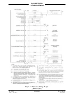
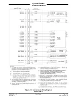
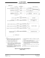
Connection to the antenna should be made in accordance with the system interconnect diagram
Figure 2-3.
2.3.5.2 L-Band Antenna
The L-band antenna is used to must meet the minimum performance requirements for the Lynx NGT-9000s.
Antennas meeting the minimum performance specifications needed by the Lynx NGT-9000s may already
be installed in the aircraft and may be available for use. Use the antenna location information below to
verify an existing antenna location is acceptable for use.
2.3.5.2.1 L-band Antenna Location
The L-band antenna installation should be installed in accordance with AC 43.12-2A Chapter 3. The
following guidance provides information to aid the installer in determining that the best location is
selected for the installation of the L-band Antenna.
•
The primary L-Band antenna (978 MHz /1030 & 1090 MHz) must be mounted vertically on the
bottom of the aircraft fuselage. The antenna shall be located to minimize obstruction to fields in the
horizontal plane.
•
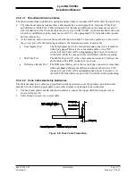
The optional Diversity L-Band antenna (1090 MHz) must be mounted vertically on the top of the
aircraft as shown in Figure 2-13. Horizontal separation from the bottom mounted L-band antenna
must be no more than 25 feet (7.6 meters).
•
The total attenuation including connectors shall not exceed 1.5 dB. Based on this, the length of the
cable can be decided assuming RG-400 cable. RG type coaxial cable insertion loss can vary
significantly between manufacturers. Refer to the cable manufacturer's specification sheet for actual
attenuation (insertion loss) for the cable being used.
•
The Antenna(s) should be located away from major protrusions, such as engine(s), propeller(s), and
antenna masts. It should be as far as practical from landing gear doors, access doors, or other
openings that could affect its radiation pattern.
•
The Antenna(s) must be mounted no closer than 20 inches from any FADEC (Full Authority Digital
Engine Control).
•
The bottom L-Band must be mounted no closer than 7 feet to any DME antenna.
•
The Antenna(s) must be mounted no closer than 36 inches to any TAS/TCAS antenna.
•
The Antenna(s) should be mounted no closer than 3 feet from any GPS antenna.
0040-17001-01
Installation
Page 2-23
Revision A
January 15, 2015

