

Lynx NGT-9000s
Installation Manual
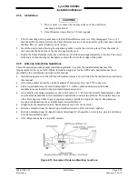
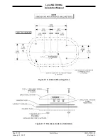
2.3.5.3 L-Band Antenna Installation
Refer to the aircraft manufacturer's data and the antenna manufacturer's installation instructions to mount
the antenna(s). The installer may use other FAA approved data to gain a separate antenna installation
approval.
•
Electrical Bonding Requirements:
Each L-Band antenna requires a minimum ground plane radius of 12 inches of contiguous metal (no
access panels, etc.) around the perimeter of the antenna. For metal aircraft, the surrounding metal
skin on which the antenna is mounted supplies the ground plane. For non-metal aircraft, the ground
plane can be composed of heavy duty aluminum foil tape, such as 3M PIN 438 or other adhesive
backed dead soft aluminum foil minimum 0.012 inches thick. It should be noted that if the antenna is
struck by lightning, the foil by itself may not be sufficient to dissipate lightning currents. Additional
protection may be needed depending on the construction of the structure to which the antenna is
mounted.
The electrical bonding requirements stated in paragraph 2.3.2 must be met.
•
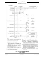
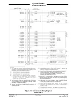
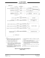
Connection to the antenna should be made in accordance with the system interconnect diagram
Figure 2-3.
•
All antenna cables should be clearly marked as both connections use TNC connectors.
•
Acceptable coaxial cable attenuation including connectors shall be less than 1.5 dB at 978 MHz.
•
Reference General Information Section – Antenna Cables for L-Band Antenna cable loss and
minimum antenna spacing requirements.
•
Refer to General Information Section - lists some suitable cable types. Any 50ohm, double-shielded
coaxial cable assembly that meets airworthiness requirements and the acceptable attenuation
requirements (including connectors) may be used. When computing cable loss, a typical loss of 0.2
dB can be used for each connection. Refer to paragraph 2.3 step 2 for antenna electrical bonding
requirements.
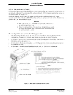
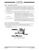
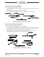
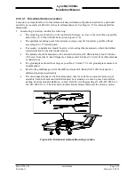
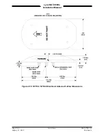
2.3.5.4 Installation Guidelines for NY156 (TCAS) and NY164 (TCAS) Directional Antenna
Connections are made through two TNC and one BNC connector. To ensure a tight seal between the
airframe and antenna, an O-ring seal (i.e., an O-ring groove for an MS28775-044 O-ring) has been
incorporated into the design. An O-ring is supplied with each antenna and must be installed when
mounting the antenna. Installation kits associated with various airframes are described in the General
Information section along with the contents of each kit.
Page 2-24
Installation
0040-17001-01
January 15, 2015
Revision A