background image

         P AR 5610 Reference Manual. Rev 1.1 


Page 28 of 35 


Conversion Mode 

With the selection box in the middle of the screen the conversion mode can be selected. 
The check box “motion adaptive” filtering is used to improve picture quality for moving 
images to reduce motion blur, and should be selected for normal use. For still images the 
checkbox should be switched off. 
 

Input Cropping 

With these controls 

it’s possible to crop the input image which will be used for conversion 

(cropping will appear on the converted image output). 
Values can be set with the numerical entry fields or with the markers on the input picture 
representative. 

Output Insertion 

With these controls the size and positioning of the output image can be set. Any parts of 
the image which has no content (cropped on the input or outside the image extents if 
shifted or made smaller) will be filled with black. 
Values can be set with the numerical entry fields or with the markers on the output picture 
representative. 

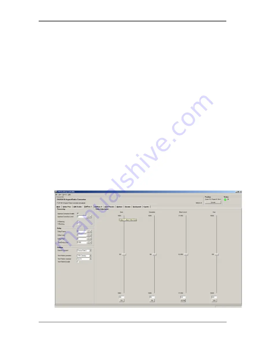
Output Proc Tabs 

There are two 

“Out Proc” tabs provided, one for each of the two outputs provided. This is 

where the individual video processing functions are set for each channel. The two tabs 
have identical adjustments. 


Summary of Contents for P AR 5610

Page 1: ...itted in any form or by any means electronic or mechanical for any purpose without express written permission of LYNX Technik AG LYNX Technik AG may have patents patent applications trademarks copyrig...

Page 2: ...Size and Positioning 9 Video Processing 10 Proc Amp Functions 10 Aperture Correction 10 Test Patterns 10 Programmable Video Delay optional OC 5610 VDLY 10 Fixed Delays 11 GPI Function 12 Freeze input...

Page 3: ...Cross Conversion OC 5610 XUPD 27 Input Aspect Ratio 27 Output Format 27 Conversion Mode 28 Input Cropping 28 Output Insertion 28 Output Proc Tabs 28 Color Space Conversion 29 Aperture Correction 29 H...

Page 4: ...rranty shall not apply to any defect failure or damage caused by improper use or improper or inadequate maintenance and care LYNX Technik shall not be obligated to furnish service under this warranty...

Page 5: ...is operated in a commercial environment This equipment generates uses and can radiate radio frequency energy and if not installed and used in accordance with the instruction manual may cause harmful...

Page 6: ...static bag unless observing adequate ESD precautions Please see below ESD Warning This product is static sensitive Please use caution and use preventative measures to prevent static discharge or damag...

Page 7: ...ormats 525 59 94Hz 1080i 59 94Hz 625 50Hz 1080i 60Hz 1080i 50Hz 720P 59 94Hz 720P 60Hz 720P 50Hz Output Video Formats The module provides four SDI outputs user assignable in two sets of two outputs th...

Page 8: ...ble image size and position Modes supported are as follows Conversion from 16 9 to 4 3 Aspect Ratios 4 3 Letterbox This takes the 16 9 aspect ratio of the input signal and fits it horizontally into th...

Page 9: ...rtion of the 4 3 input signal and fills the 16 9 SD image area cropping the top and bottom of the image 16 9 Stretch to Fill This mode takes the 4 3 input signal and distorts horizontally stretches th...

Page 10: ...into each output The Test pattern will follow the selected output standard selected for each channel The selected test pattern is also available as one of the modes the synchronizer will switch to whe...

Page 11: ...40 1080i59 94 1080i59 94 1 33 720p50 720p50 1 p 20 720p59 94 720p59 94 1 p 16 SDTV Aspect Ratio Conversion 525 525 2 66 625 625 2 80 Down Conversion if OC 5610_UPXD option is installed 1080i50 625 3...

Page 12: ...ons will be performed With GPI open the module processes the input signal as usual With GPI closed the input will be frozen volatile freeze i e frozen frame is not retained through power cycle In the...

Page 13: ...mmend the use of high quality video cable for digital video connections to reduce the risk of errors due to excessive cable attenuation Max cable lengths the module will support are shown below SDTV 2...

Page 14: ...anual Rev 1 1 Page 14 of 35 Module Layout Module Front Panel Module Rear Termination Panel Note Cooling fan operation is monitored and alarmed with the module alarm LED and also within the LYNX contro...

Page 15: ...down before installing any additional modules into an existing card frame 1 Select a free two slot space in the card frame where the CardModule will be located 2 Remove the blank connection panels fr...

Page 16: ...ing the control system to quickly re purpose the modules settings The GPI can also be configured to toggle between any 2 of the 4 stored presets if required Metadata Option OC 5610 META This option pr...

Page 17: ...put Signal Converted to 1080i 59 94Hz or 720P 59 94Hz 625 50Hz Input Signal Converted to 1080i 50Hz or 720P 50Hz Modes of operation are as follows 16 9 Center Cut This mode cuts the horizontal center...

Page 18: ...also provides the ability to manually adjust the image size and position of the converted output For more information on the controls and use of this feature please refer to the GUI section of this ma...

Page 19: ...ol provided Some basic module settings are possible via the local controls which are detailed below Once set all settings are automatically saved in non volatile internal memory Flash RAM The module w...

Page 20: ...ies the first value displayed will be the value currently stored in the system The order of the available settings for any menu item in the table supplied does not represent the order the settings wil...

Page 21: ...15 Grey WHTE White YELL Yellow MGNT Magenta CYAN Cyan BLUE Blue GREE Green RED Red BLK Black back noIN Output if no Input BLCK Black PATT Testpattern back back back CONV MODE Conversion Mode FILL Str...

Page 22: ...Preset Settings LOAD Load User Preset to Current PRE1 Preset 1 PRE2 Preset 2 PRE3 Preset 3 back Gon GPI on settings CURR Current PRE1 Preset 1 PRE2 Preset 2 PRE3 Preset 3 back Goff GPI Off settings CU...

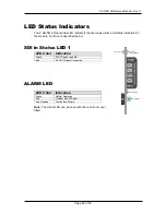
Page 23: ...tatus indication for the module Function is described below SDI in Status LED 1 ALARM LED LED Color Indication Green Normal Operation Red Problem with SDI input Red Flashing Cooling Fan Failure Note T...

Page 24: ...area contains information about the module including name and firmware revision If used as part of a larger system using the LYNX central control system the modules position and physical location is d...

Page 25: ...avigation to other areas Input standards and formats are auto detected and displayed in the GUI Parameters will be annunciated in different colors to show status green good red problem yellow caution...

Page 26: ...onfiguration screen for the GPI functions GPI influence Device Status This area is used to show the detected internal FPGA and external temperature board of the Module If the internal temperature exce...

Page 27: ...also provides Down Conversion functionality as described previously The screen below shows the controls provided for the HQ Up Down Cross and Aspect Ratio Conversion Input Aspect Ratio For SD input S...

Page 28: ...converted image output Values can be set with the numerical entry fields or with the markers on the input picture representative Output Insertion With these controls the size and positioning of the o...

Page 29: ...range H and V Blanking A checkbox selection is provided for H Horizontal and V Vertical blanking When selected the video output will have new blanking applied in both of these areas which will overwr...

Page 30: ...drop down selection provided The pre selected pattern will be used if the freeze mode is set to test pattern and will also the pattern used if test pattern on is selected Patterns provided are Full f...

Page 31: ...ault null settings are 0 this is the default Sliders can be quickly returned to the factory null or transparent settings using the buttons provided at the bottom of each slider User Presets optional O...

Page 32: ...ould like to add any option after delivery then you will need to purchase the specific license codes from LYNX Technik Click the request code button next to the channel you wish to activate A number w...

Page 33: ...y default all alarm conditions are activated checked by de selecting a specific alarm condition I this column you are telling the module to ignore this condition completely It will not color the alarm...

Page 34: ...ments Independent for all 2 outputs optional Minimum delay Variable depending on selected functionality and installed options Please refer to Fixed Video Delays table in this manual Video adjustments...

Page 35: ...available from our website Please do not return products to LYNX without an RMA Please contact your authorized dealer or reseller for more details More detailed product information and product update...

Reviews: