background image

CONTROLS, INSTRUMENTS AND EQUIPMENT

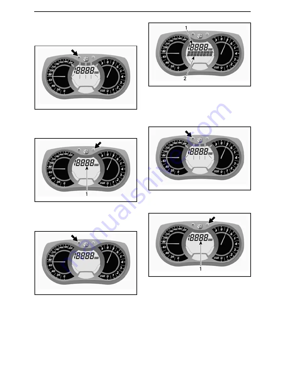
Use MODE (M) button to select the de-

sired display, then proceed as follows:

mmo2007-009-066_m

While display is flashing, press the

SET (S) button to select speedometer

mode.

mmo2007-009-066_n

1. Speedometer mode

Press the MODE (M) button to confirm

selection or wait 5 seconds.

mmo2007-009-066_o

B) Tachometer (RPM)

In addition of the analog type tachome-

ter, RPsM can also be displayed via the

multifunction display.
Engine RPM can be displayed on dis-

play 1 or display 2.

mmo2007-009-066_q

MULTIFUNCTION DISPLAY

1. Display 1
2. Display 2

Use MODE (M) button to select the de-

sired display, then proceed as follows:

mmo2007-009-066_m

While display is flashing, press SET (S)

button to select RPM mode.

mmo2007-009-066_n

1. RPM mode

Press the MODE (M) button to confirm

selection or wait 5 seconds.

32

______________

Summary of Contents for RAVE RS SERIES

Page 1: ......

Page 2: ...ime to familiarize yourself with your new vehicle OPERATOR S MANUAL 2012 Rave RSTM 600 Lynx products are manufactured by BRP The following are trademarks of Bombardier Recreational Products Inc or its sub sidiaries HPG RAVE ROTAX TRA RS Lynx XPS The KYB Pro series is a registered mark of KYB America LLC fmo2012 en TM and the BRP logo are trademarks of Bombardier Recreational Products Inc or its af...

Page 3: ...fety Messages The types of safety messages what they look like and how they are used in this guide are explained as follows WARNING Indicates a potential hazard if not avoided could result in serious in jury or death CAUTION Indicates a hazard situation which if not avoided could result in minor or moderate injury NOTICE Indicates an instruction which if not followed could se verely damage vehicle...

Page 4: ... them on prod ucts previously manufactured Due to late changes some differences be tween the manufactured product and the descriptions and or specifications in this guide may occur BRP reserves the right at any time to discontinue or change specifications designs fea tures models or equipment without incurring any obligation upon itself This Operator s Guide should remain with the vehicle when it ...

Page 5: ...g Variations 15 Environment 19 IMPORTANT ON PRODUCT LABELS 22 Premix Fuel Oil Ratio 22 VEHICLE INFORMATION CONTROLS INSTRUMENTS AND EQUIPMENT 24 1 Handlebar 25 2 Throttle Lever 25 3 Brake Lever 25 4 Parking Brake Lever 25 5 Engine Cut off Switch 26 6 Emergency Engine Stop Switch 26 7 Primer Button 27 8 Rewind Starter Handle 27 9 Pre Heat Switch 27 10 High Beam Low Beam Switch 27 11 Heated Grips He...

Page 6: ...ting Procedure 50 TUNE YOUR RIDE 52 Rear Suspension Adjustments 52 Front Suspension Adjustments 57 Adjustment Tips According to Vehicle Behavior 59 VEHICLE TRANSPORTATION 60 MAINTENANCE INFORMATION BREAK IN INSPECTION 62 PERIODIC MAINTENANCE CHART 63 MAINTENANCE SCHEDULE 2 STROKE 64 PRESEASON PREPARATION 66 STORAGE 67 MAINTENANCE PROCEDURES 68 Throttle Position Sensor TPS 68 Air Filter 68 Engine C...

Page 7: ...TIFICATION 86 Vehicle Description Decal 86 Identification Numbers 86 EC DECLARATION OF CONFORMITY 87 SPECIFICATIONS 88 TROUBLESHOOTING TECHNICAL GUIDELINES 92 MONITORING SYSTEM 94 Pilot Lamps Messages and Beeper Codes 94 Fault Codes 95 WARRANTY LIMITED WARRANTY VALIDATION 98 BRP FINLAND OY INTERNATIONAL LIMITED WARRANTY 2012 LYNX SNOWMOBILES 99 CUSTOMER INFORMATION PRIVACY INFORMATION 104 CHANGE O...

Page 8: ...TABLE OF CONTENTS 6 _______________ ...

Page 9: ...SAFETY INFORMATION ________ SAFETY INFORMATION ________ 7 ...

Page 10: ...ad and be ignited by a spark or flame many feet away from the en gine To reduce the risk of fire or explo sion follow these instructions Use only an approved gasoline con tainer to store fuel Strictly adhere to instructions in FU ELING PROCEDURE Never start or operate the engine if the fuel cap is not properly installed Gasoline is poisonous and can cause injury or death Never siphon gasoline by m...

Page 11: ...e or provincial safety training program Any new operator must read and understand all safety labels on the snowmo bile the Operator s Guide before operating the snowmobile Only allow a new operator to operate the snowmobile in a restricted flat area at least until he is completely familiar with its operation If snowmobile operator s training course is offered in your area have him enroll The perfo...

Page 12: ...bility be extra cautious Avoid unfamiliar terrain and be sure your lights are working Always carry a flashlight and spare light bulbs Never remove any original equipment from your snowmobile Each vehicle has many built in safety features Such features include various guards and consoles plus reflective materials and safety labels Nature is wonderful but don t let it distract your attention from dr...

Page 13: ...ho rized use by children or others or theft NEVER stand behind or near a rotating track Debris could be projected causing severe injuries To remove packed snow or ice stop engine tilt and hold vehicle on its side and use screwdriver Do not stud the track unless it has been approved for studs At speed a studded track that has not been approved for studs could tear and separate from vehicle See an a...

Page 14: ... important prior to operating the vehicle Always check the proper operation of critical controls safety features and mechanical components before starting Before Starting the Engine 1 Remove snow and ice from body in cluding lights seat footrests con trols and instruments 2 Verify that air silencer prefilter is free of snow 3 Verify that skis and steering operate freely Check corresponding action ...

Page 15: ...remove snow or ice Air silencer prefilter Check condition and remove snow or ice Steering system Check for free movement and proper action Skis and runners Check condition Fuel Check level and replenish if necessary Coolant Check level If low contact an authorized Lynx dealer Brake fluid Check level A low fluid level indicates a leak or worn brake pads Contact an authorized Lynx dealer Storage com...

Page 16: ...rels that could get caught in moving parts What to Bring First aid kit Mobile phone Knife Spare spark plugs Flashlight Friction tape Trail map Spare drive belt Snack Toolkit Rider Position Forward Operation Your riding position and balance are the two basic principles of making your snowmobile go where you want it to When turning on the side of a hill you must be ready to shift body weight to help...

Page 17: ...our weight could shift forward against throttle lever while operating in reverse causing an unexpected acceleration WARNING Unexpected acceleration when snowmobile operates in reverse can cause a loss of control Carrying a Passenger Certain snowmobiles are designed for an operator only 1 UP and others can allow one passenger only 2 UP Make sure to identify and respect the warn ings according to yo...

Page 18: ...id waterways If you are in an unfamiliar area ask the local author ities or residents about the ice condi tion inlets outlets springs fast mov ing currents or other hazards Never attempt to operate your snowmobile on ice that may be too weak to sup port you and the vehicle Operating a snowmobile on ice or icy surfaces can be very dangerous if you do not observe certain precautions The very nature ...

Page 19: ...og or Whiteout Conditions On land or water fog or visibility lim iting snow can form If you have to proceed into the fog or heavy snow do so slowly with your lights on and watch intently for hazards If you are not sure of your way do not proceed Keep a safe distance behind other snowmo bilers to improve visibility and reaction time Unfamiliar Territory Whenever you enter an area that is new to you...

Page 20: ...und Do not over exert yourself Get assis tance Remember to always lift using your legs as opposed to your back fmo2008 003 005 Road Crossing In some cases you will be approach ing the road from a ditch or snowbank Choose a place where you know you can climb without difficulty Use the standing position and proceed with only as much speed needed to crest the bank Stop completely at the top of the ba...

Page 21: ...will reduce the hazard to other snowmobilers using the trail Trails and Signs Trail signs are used to control direct or regulate the use of snowmobiles on trails Become familiar with all signs used in the area where you are snow mobiling Environment Wildlife compliments your snowmo biling day Snowmobile tracks provide firm ground over which animals can travel from area to area Do not violate this ...

Page 22: ...ub lic land agencies Learn the rules and follow them and that goes for speed limits too Avoid running over young trees shrubs and grasses and don t cut wood On flatlands or areas where trail riding is popular it s important to ride only where authorized Remember there is a link between protecting your environment and your own safety Respect wildlife and be particularly sensitive of animals that ar...

Page 23: ...racks or careen through a virgin forest to show you can ride So whether you re driving a high perfor manceLynx a sporty RAVE snowmo bile or any other make or model show you know what you re doing Show you know how to send snow flying and make tracks with a light touch ________ SAFETY INFORMATION ________ 21 ...

Page 24: ...IMPORTANT ON PRODUCT LABELS Premix Fuel Oil Ratio NOTICE Warning label on the vehicle NOTICE Fuel oil label on the vehi cle 22 _______ SAFETY INFORMATION ________ ...

Page 25: ...VEHICLE INFORMATION _______________ 23 ...

Page 26: ...CONTROLS INSTRUMENTS AND EQUIPMENT fmo2011 007 007_c fmo2011 007 010_d fmo2011 007 011_a 24 ______________ ...

Page 27: ...pplied on the lever and to the type of terrain and its snow coverage 4 Parking Brake Lever Parking brake is located on the LH side of handlebar Parking brake should be used when ever snowmobile is parked WARNING Make sure parking brake is fully disengaged before operating the snowmobile When you ride the vehicle brake pads that are caused to drag by a continuous pressure on the lever may cause dam...

Page 28: ...YPICAL 1 Snap over post 2 Attach to clothing If emergency engine shut off is re quired pull tether cord cap from post completely 6 Emergency Engine Stop Switch The emergency engine stop switch is located on the RH side of handlebar To stop the engine in an emergency select OFF position down and simul taneously apply the brake mmo2007 009 038_a OFF POSITION To allow engine starting the switch must ...

Page 29: ... of sticking 8 Rewind Starter Handle Auto rewind type located on right hand side of snowmobile To engage mech anism pull handle slowly until a re sistance is felt then pull vigorously Slowly release handle 9 Pre Heat Switch Racing Application Only NOTE This switch must be removed on vehicles modified for warranty vali dation 1 A33E0SA 2 1 Button depressed Pre heat timing curve 2 Button released No...

Page 30: ...ction digital display 4 Pilot lamps 5 Mode button 6 Set button NOTE The gauge is factory preset in metric units but it is possible to change it to Imperial units contact an autho rized Lynx dealer for unit settings 1 Speedometer Measures vehicle speed mmo2008 007 017 LH PORTION OF GAUGE 2 Tachometer RPM Measures engine revolution per minute RPM Multiply by 1000 to ob tain the actual revolutions mm...

Page 31: ...rolling messages of func tion activation or system faults Display fault codes When the information center is first powered up the numerical display de faults to the last selected indication WARNING Never adjust or set functions on the multifunction gauge while rid ing the vehicle 4 Pilot Lamps and Messages mmo2008 003 024_a TYPICAL PILOT LAMPS See table below for usual pilot lamps information Refe...

Page 32: ...ERSE Reverse is selected 3 short beeps REV FAIL Reverse did not engage try again High beam headlights are selected WARM UP Engine and or injection oil need to warm up before normal operation The engine s RPM is limited until desired temperature is reached up to 10 minutes when driving Warm up period may occur after a restart in very cold weather 5 MODE M Button Button use to navigate in gauge mult...

Page 33: ...mption X I Total fuel consumption X J Message display X K Top RPM X L Lap record mode X M Exhaust gas temperature X N Throttle position display X X An X indicates a standard feature A Speedometer In addition of the analog type speedometer vehicle speed can also be displayed via the multifunction display Vehicle speed can be displayed on dis play 1 or display 2 mmo2007 009 066_q MULTIFUNCTION DISPL...

Page 34: ... 009 066_o B Tachometer RPM In addition of the analog type tachome ter RPsM can also be displayed via the multifunction display Engine RPM can be displayed on dis play 1 or display 2 mmo2007 009 066_q MULTIFUNCTION DISPLAY 1 Display 1 2 Display 2 Use MODE M button to select the de sired display then proceed as follows mmo2007 009 066_m While display is flashing press SET S button to select RPM mod...

Page 35: ...P B mode mmo2007 009 066_p 1 Trip meter TRIP A TRIP B mode Press and hold the SET S button to re set mmo2007 009 066_k E Trip Hour Meter Records vehicle running time when the electrical system is activated since it has been reset Press the SET S button to select trip hour meter HrTRIP mode mmo2007 009 066_p 1 Trip hour meter HrTRIP mode Press and hold the SET S button to re set mmo2007 009 066_k F...

Page 36: ...5 seconds mmo2007 009 066_o To reset press the MODE M to select mode mmo2007 009 066_m While display flashes press and hold the SET S button within 5 seconds to reset mmo2007 009 066_w G Average Speed Records vehicle average speed since it has been reset To display vehicle average speed pro ceed as follows Press the MODE M button to select display 1 mmo2007 009 066_m While display flashes press SE...

Page 37: ...S button within 5 seconds to reset mmo2007 009 066_w H Instant Fuel Consumption Calculates vehicle average fuel con sumption while riding To display vehicle average fuel con sumption proceed as follows Press the MODE M button to select display 1 mmo2007 009 066_m While display flashes press SET S button to select instant fuel consump tion mode mmo2007 009 066_n 1 Instant fuel consumption mode Pres...

Page 38: ...While display flashes press the SET S button to select total fuel consump tion TC mode mmo2007 009 066_n 1 Total fuel consumption TC mode TC appears when the mode is se lected mmo2008 003 021_a TYPICAL Press the MODE M button to confirm selection or wait 5 seconds mmo2007 009 066_o To reset set the trip meter to TRIP B Refer to TRIP METER A OR B for more details mmo2007 009 066_p 1 Trip meter TRIP...

Page 39: ...ute proceed as follows 1 Press the MODE M button to se lect display mmo2007 009 066_m NOTE Display will flash for approxi mately 5 seconds then will return to the previously selected mode if display is not changed 2 While display flashes press the SET S button to scroll and select top RPM TOP_RPM mode mmo2007 009 066_n 1 Top RPM TOP_RPM mode 3 Press the MODE M button to con firm selection or wait ...

Page 40: ...per minute RPM 5 Preselected function To Activate Lap Record Mode 1 Press the SET S button to select the odometer mode in display 3 2 Press and hold SET S button for 2 seconds to activate mode REC will be displayed to indicate that record mode has been selected mmo2009 009 002_a 1 Record mode 2 Odometer 3 Press the SET S button to scroll be tween modes Available modes are STOP REC record or PLAY T...

Page 41: ...ally to the following recorded lap after 5 seconds At the end of all recorded laps STOP will appear in display To review recorded data again press the SET S button to return to PLAY mode Repeat same procedure previ ously described to review To record other laps press the SET S button to switch to REC record mode Repeat same procedure previously de scribed to record Press and hold SET S button for ...

Page 42: ...on within 5 seconds to reset mmo2007 009 066_w N Throttle Position Display Displays real time throttle opening in percentage from approximately 0 to 100 To display throttle position proceed as follows 1 Press the MODE M button to se lect display mmo2007 009 066_m NOTE Display will flash for approxi mately 5 seconds then will return to the previously selected mode if display is not changed 2 While ...

Page 43: ...9 009 006_a REAR 1 Rear bumper NOTICE Do not use skis to pull or lift snowmobile 14 Drive Belt Guard Drive Belt Guard Removal WARNING NEVER operate engine Without shields and belt guard securely installed With hood and or side panels opened or removed NEVER attempt to make adjust ments to moving parts while en gine is running NOTE Belt guard is purposely made slightly oversize to maintain tension ...

Page 44: ...ot mmo2009 003 010_a 1 Tabs Position the grommet over the retain ing rod It may be necessary to slightly lift the console to make room mmo2009 003 011_a 1 Retaining rod Position rear portion of belt guard over retainer and secure it using retaining pin mmo2008 007 016_a 1 Retaining pin 15 Spare Drive Belt Holder A spare drive belt can be stored in holder NOTE Spare drive belt is not supplied with ...

Page 45: ...VELCRO STRAP 16 Hood WARNING Never operate engine with hood removed from vehicle To open hood release hood retaining pins then slide hood towards the front of the vehicle fmo2012 009 001 Step 1 Release retaining pins Step 2 Slide hood towards the front 17 Side Panels WARNING Never operate engine with side panels opened or removed from vehicle To open a side panel stretch and un hook the latches mm...

Page 46: ...CONTROLS INSTRUMENTS AND EQUIPMENT To remove a side panel open it then lift it up Free the lower hinge from its slot then free the upper hinge by lowering the panel 44 ______________ ...

Page 47: ... should be not used When using non oxygenated fuel we highly recommend the use of isopropyl base gas line antifreeze in a proportion of 150 ml 5 U S oz of gas line an tifreeze added to 40 L 10 U S gal of gas This precaution is in order to reduce the risk of frost buildup in carburetors or other fuel system components which may lead in certain cases to high fuel consumption or severe damage to en g...

Page 48: ...ith fuel at the ratio of 33 1 in a jerry can then be poured in the fuel tank Refer to PREMIX FUEL OIL RATIO ta ble below as a guideline to properly premix oil with fuel NOTICE Never experiment with other fuel oil ratios Use only oil that can flow at 40 C 40 F Use only two stroke engine injection oil sold by authorized Lynx dealers 2 STROKE ENGINE INJECTION OIL XPS SYNTHETIC 2 STROKE OIL P N 619 59...

Page 49: ...id sustained accelerations Avoid prolonged cruising speeds Avoid engine overheating However brief accelerations and speed variations contribute to a good break in During the first few hours of break in the engine management system con trols some engine parameters which will slightly reduce the engine perfor mance Drive Belt A new drive belt requires a break in pe riod of 50 km 30 mi During the bre...

Page 50: ...tes at idle speed NOTE It is not recommended to let engine running at idle speed for more than 10 minutes 3 Disengage parking brake 4 Apply throttle until drive pulley en gages Drive at low speed the first two or three minutes NOTICE If vehicle does not move when throttle is applied remove tether cord cap then do the follow ing Check if skis are stuck on the ground Lift one ski at a time by the ha...

Page 51: ...o an authorized Lynx dealer Hard Packed Snow This snowmobile s track has a lug pro file of 44 mm 1 732 in and BRP does not recommend to ride it at high speed on a trail hard packed snow or ice In the event that you have to ride on such surfaces reduce your speed and minimize the travel distance NOTICE Running that type of track at high speeds on a trail on hard packed surfaces or ice puts more str...

Page 52: ... some one sit on the towed snowmobile to ac tivate the brake and tow at low speed NOTICE In order to prevent dam age to the steering system never attach the tow rope to the ski loops handles WARNING Never ride at high speed when towing a disabled snowmobile Proceed slowly with extra caution Emergency Starting Procedure The engine can be started with an emergency starter rope Remove drive belt guar...

Page 53: ...d pulley must rotate counterclockwise mmo2008 005 014_a Pull the rope using a sharp crisp pull so the rope comes free of the drive pulley Start engine as per usual manual start ing WARNING When starting the snowmobile in an emergency situation using drive pulley do not reinstall the drive belt guard and return slowly to have snowmobile repaired _______________ 51 ...

Page 54: ... the ground with a wide base snow mobile stand with a rear deflec tor panel Make sure support device is sta ble and secure The best way to set up the suspen sion is to customize each adjustment one at a time Various adjustments are interrelated It may be necessary to readjust center spring after adjust ing front springs for instance Test run the snowmobile under the same con ditions trail speed sn...

Page 55: ...ore than 75 mm 3 in Adjusted too soft increase preload Less than 50 mm 2 in Adjusted too firm decrease preload NOTE If the specification is unattain able with the original springs see an authorized Lynx dealer for other avail able springs fmo2012 005 502_a 1 Rear spring 2 Adjust spring preload Center Spring Center spring preload has an effect on steering effort handling and bump ab sorption Also s...

Page 56: ...pper Strap Stopper strap length has an effect on the amount of weight the center spring has to carry especially during accelera tion therefore on the front end uplift Stopper strap length also has an effect on center spring travel NOTICE Whenever stopper strap length is changed track tension must be checked 54 ______________ ...

Page 57: ...will dictate the most efficient combination Generally a longer stopper strap set ting gives better performance in deep snow on a flat landscape Rear Shock Low Speed Compression Damping Low speed compression damping con trols how the shock absorber reacts to a low suspension velocity slow com pression strokes in most cases when riding at lower speeds ACTION RESULT ON BIG BUMPS Increasing low speed ...

Page 58: ...TION RESULT ON BIG BUMPS Increasing low speed compression damping force Firmer compression damping slow compression Decreasing low speed compression damping force Softer compression damping slow compression To adjust turn clockwise to increase damping force and counterclockwise to decrease damping force fmo2012 005 505_a 1 Center shock absorber 2 Low speed compression damping adjuster knob or slot...

Page 59: ...eload Less bump absorption capability mmo2010 003 027_a TYPICAL RING TYPE 1 Decrease preload 2 Increase preload 3 Spring preload adjustment ring NOTICE Make sure that both front springs are still pre loaded when front of vehicle is off the ground Front Shock Absorbers Low Speed Compression Damping Low speed compression damping con trols how the shock absorber reacts to a low suspension velocity sl...

Page 60: ...rce Softer compression damping fast compression To adjust turn clockwise to increase damping force and counterclockwise to decrease damping force mmo2010 003 020_b 1 High speed compression damping adjuster hexagonal Rebound Damping Rebound damping controls how the shock absorber restrains the exten sion stroke ACTION RESULT Increasing rebound damping force Firmer rebound damping extension stroke D...

Page 61: ...ornering or acceleration Shorten limiter strap Increase rear spring preload Rear of snowmobile seems too stiff Reduce rear spring preload Reduce compression damping adjustment if applicable Rear of snowmobile seems too soft Increase rear spring preload Rear suspension is frequently bottoming Increase rear spring preload Increase center spring preload Lengthen limiter strap Increase compression dam...

Page 62: ...asy to do as it may seem many seri ous accidents have resulted from driving up and over a trailer Anchor your vehicle securely front and rear even on short hauls Be certain all equipment is securely fastened Cover your snowmobile when trailer ing to prevent road grime from causing damage Be certain your trailer meets state or provincial requirements Ensure the hitch and safety chains are secure an...

Page 63: ...MAINTENANCE INFORMATION _______________ 61 ...

Page 64: ...e cable Inspect oil injection pump adjustment All except E TEC Inspect drive belt Visually inspect drive pulley Tighten drive pulley retaining screw to specified torque Inspect driven pulley Inspect spark plugs All except E TEC Adjust and align track Change chaincase gearbox oil Retorque gearbox cover screws both sides of speedometer sensor connector to 10Nm Only XU Models Adjust drive chain Not f...

Page 65: ... before performing any mainte nance or adjustment unless otherwise specified Vehicle must be parked in a safe place away from the trail WARNING Observe WARNINGS and CAUTIONS mentioned throughout this guide which are relevant to the item being checked When component conditions seem less than satisfactory replace with genuine BRP parts or approved equivalents Some items may not apply to your particu...

Page 66: ...ng system cap hoses and clamps and check for leaks Replace spark plugs All except of E TEC Clean RAVE valves Inspect RAVE valves solenoid Adjust engine stopper Visually inspect and clean drive pulley Tighten drive pulley retaining screw to specified torque Clean driven pulley Adjust and align track Inspect brake hose pads and disk Inspect steering mechanism Inspect front suspension Inspect rear su...

Page 67: ...cessary Replace spark plugs 800 E TEC only Replace brake fluid Inspect throttle cable EVERY 10 000 KM OR 3 YEARS WHICHEVER COMES FIRST Replace oil filter E TEC Inspect oil pump strainer and clean if needed Replace spark plugs 600 E TEC only EVERY 5 YEARS Replace in line fuel filter Replace engine coolant _______________ 65 ...

Page 68: ...ions Clean and inspect throttle body Inspect throttle cable Inspect drive belt adjust at every drive belt replacement Clean and visually inspect drive pulley Clean and inspect driven pulley Inspect adjust and align track Adjust drive chain Not for models equipped with gearbox Change chaincase gearbox oil Check brake fluid level Inspect brake hose pads and disk Inspect steering mechanism Inspect sk...

Page 69: ...ions Run the engine after adding the product to the fuel 2 Stroke models Lubricate engine See owners manual for instruction Lubricate brake lever pivot Inspect and lubricate rear suspension Charge battery monthly to keep it fully charge during storage Block muffler with rags Lift rear of vehicle until track is clear of the ground Do not release track tension Lubricate front and rear suspension ___...

Page 70: ...lways replace with a new one Throttle Position Sensor TPS Throttle Position Sensor Reset To reset TPS proceed as follows 1 Refer to CONTROLS INSTRU MENTS AND EQUIPMENT and open the RH side panel 2 Remove the 6 pin vehicle connector from its protective cap on the RH side 3 Connect the T HARNESS P N 529 035 869 on the 6 pin connector 4 Connect the T harness to a 12 V bat tery using the 12 V BATTERY ...

Page 71: ...tion aluminum engines Cooling system must be filled with BRP PREMIXED COOLANT P N 219 700 362 or with distilled water and an tifreeze solution 50 distilled water 50 antifreeze Exhaust System Exhaust System Verification The muffler tail pipe should be cen tered with the exit hole in the bottom pan Exhaust system must be free of rust or leaks Make sure that all parts are securely in place Check reta...

Page 72: ...tment The engine stopper is located on the LH front engine support in front of the drive pulley 1 Remove the tether cord cap 2 Remove the LH side panel refer to CONTROLS INSTRUMENTS AND EQUIPMENT 3 Remove drive belt guard refer to DRIVE BELT GUARD REMOVAL in CONTROLS INSTRUMENTS AND EQUIPMENT 4 Loosen the three bolts retaining the engine stopper to the engine sup port without removing them mmo2009...

Page 73: ... of contact with the eyes immediately rinse with plenty of water for at least 10 min utes and then consult a doctor im mediately Chaincase Oil Recommended Chaincase Oil Use XPS SYNTHETIC CHAINCASE OIL P N 413 803 300 NOTICE Use only the recom mended type oil when servicing Do not mix synthetic oil with other types of oil Chaincase Oil Level With the vehicle on a level surface check the oil level b...

Page 74: ...ive Belt Removal 1 Remove tether cord cap Open LH side panel refer to CON TROLS INSTRUMENTS AND EQUIP MENT 2 Remove belt guard refer to BELT GUARD REMOVAL 3 Insert the drive belt installer re mover provided in the tool box in the threaded hole on the adjuster hub A33B0SA DRIVE BELT INSTALLER REMOVER TOOL A33D1AA 4 Open the driven pulley by screwing the tool in 5 Remove the belt by slipping it over...

Page 75: ...tment must be per formed every time a new belt is in stalled To adjust the drive belt proceed as fol lows 1 Remove the tether cord cap 2 Open LH side panel refer to CON TROLS INSTRUMENTS AND EQUIPMENT 3 Remove belt guard refer to DRIVE BELT GUARD REMOVAL 4 Keep the set screw from turning using a 1 8 inch Allen wrench and loosen the lock nut using a 7 16 in open wrench 5 Turn the set screw 1 4 turn...

Page 76: ...ding 11 3 kg 25 lb 8 Adjust as required Drive Pulley Drive Pulley Adjustment WARNING Remove the tether cord cap be fore performing any maintenance or adjustment unless otherwise specified Vehicle must be parked in a safe place away from the trail General The drive pulley is factory calibrated to transmit maximum engine power at a predefined RPM Factors such as am bient temperature altitude or surf...

Page 77: ...ation screw otherwise internal washers will fall off Al ways adjust all 3 calibration screws and make sure they are all set to the same position A16D0HA 1 TYPICAL 1 Loosen just enough to permit rotating of calibrate screw WARNING NEVER disassemble or modify the drive pulley Improper assembly or modifica tions could cause the pulley to ex plode violently under the stress generated by the high rotat...

Page 78: ...Missing track guide s Also ensure that studs nut are tighten to the recommended torque On approved studded tracks replace broken or damaged studs immediately If your track shows signs of deteriora tion it must be replaced immediately When in doubt ask your dealer WARNING Riding with a damaged track or studs could lead to a loss of con trol resulting in a risk of serious injury or death For complet...

Page 79: ...lider shoe 8 Read load recorded by the upper O ring on the tensiometer mmr2009 133 003_a LOAD READING 1 Upper O ring Load reading must be as per the follow ing table TRACK ADJUSTMENT SPECIFICATION Track deflection setting 45 mm 60 mm 1 772 in 2 362 in Track load reading 6 0 kgf to 8 5 kgf 13 lbf to 19 lbf 9 If load reading is not in accordance with the specification adjust track tension Refer to T...

Page 80: ...ignment ensure that the track is free of all particles which could be thrown out while track is rotating Keep hands tools feet and clothing clear of track Always lift the snow mobile on a wide base stand with a rear deflector panel Ensure no one is standing in close proximity to the snowmobile especially at the rear of the track Never rotate track at high speed Centrifugal force could cause de bri...

Page 81: ...N m 6 N m 35 lbf ft 4 lbf ft 5 Restart engine and rotate track slowly to recheck alignment 6 Reposition snowmobile on ground 7 Install rear wheel caps if so equipped Suspension Rear Suspension Condition Visually inspect all suspension compo nents including slider shoes springs wheels etc NOTE During normal driving snow will act as a lubricant and coolant for the slider shoes Extensive riding on ic...

Page 82: ...es circuits are protected with a fuse Check fuse condition and replace it if necessary To remove fuse from holder pull fuse out Check if filament is melted 1 2 A15E0KA 1 Fuse 2 Check if melted NOTICE Do not use a higher rated fuse as this can cause severe dam age to electrical components and or be a potential fire WARNING If fuse has burnt out source of mal function should be determined and correc...

Page 83: ... pull on multifunction gauge and set aside mmo2007 009 062_a Disconnect burnt bulb connector Re move the rubber boot mmo2007 009 022_a 1 Rubber boot Press and pull both sides of the retain ing clip at the same time to release it from bulb support mmo2007 009 063_a Step 1 Push both sides in Step 2 Pull to release 1 Retaining clip Pull bulb and replace Properly reinstall parts mmo2007 009 064_a PULL...

Page 84: ... and housing will have to be replaced Do not pull taillight hous ing out too far to avoid damaging wiring mmr2008 039 006_a 1 Taillight housing retaining pins 2 Retaining grommets 3 Light wire harness 2 Rotate bulb socket counterclock wise to remove it from taillight hous ing 3 Push in and rotate bulb counter clockwise to remove it from its socket 4 Install the new bulb by pushing it in the socket...

Page 85: ...e entire vehicle use only flannel cloths or equivalent NOTICE It is necessary to use flan nel cloths or equivalent on wind shield and hood to avoid scratching the surfaces To remove grease oil and grime use BRP HEAVY DUTY CLEANER P N 293 110 001 NOTICE Do not use Heavy duty cleaner on decals or vinyl To remove stubborn dirt from all plastic and vinyl surfaces use XPS MULTI PURPOSE CLEANER P N 219 ...

Page 86: ...eeze deteriora tion The antifreeze replacement and a den sity test should be performed by an au thorized LYNX dealer CAUTION Improper antifreeze mixture might allow freezing of the liquid in the cooling system if vehi cle is stored in area where freezing point is reached This would seri ously damage the engine Failure to replace the antifreeze for storage may allow its degradation that could resul...

Page 87: ...TECHNICAL INFORMATION _______________ 85 ...

Page 88: ...the authorized Lynx dealer to complete warranty claims properly No warranty will be allowed by BRP if the engine identification number or vehicle iden tification number VIN is removed or mutilated in any way We strongly rec ommend that you take note of all the identification numbers on your snow mobile and supply them to your insur ance company Vehicle Identification Number VIN VIN is scribed on v...

Page 89: ..._______________ 87 ...

Page 90: ...ne glycol water mix 50 coolant 50 distilled water Use BRP premix coolant or coolant specifically designed for aluminum engines Cooling system capacity 4 5 L 4 8 qt U S liq Recommended fuel type Premium unleaded Minimum octane rating Outside North America 98 RON E5 Fuel tank capacity 22 L 5 81 U S gal Water pump shaft oil P N 413 802 900 DRIVE SYSTEM Drive pulley type TRA III light Driven pulley ty...

Page 91: ... 7 3 kg 16 lb Track alignment Equal distance between edges of track guides and slider shoes Drive belt part number 417 300 425 3 SUSPENSION Front suspension A LFS Front shock KYB 40 PB HLCR Front suspension max travel 242 mm 9 5 in Rear suspension PPS 3300 Front arm shock KYB 46 PB HLCR Rear arm shock KYB 46 PB HLCR Rear suspension max travel 390 mm 15 354 in ELECTRICAL SYSTEM Lightning system out...

Page 92: ...2 in 1 Measure gap between slider shoe and bottom inside of track when exerting a downward pull to the track 2 NOTICE Do not attempt to adjust gap on this type of spark plug 3 Drive belt height must be adjusted every time a new drive belt is installed Confirm drive belt part number application with an authorized Lynx dealer 4 Trail riding check your local regulations and set skis at the narrowest ...

Page 93: ...TROUBLESHOOTING _______________ 91 ...

Page 94: ... nections Possible failure of the fuel pump or carburetor Contact an autho rized Lynx dealer 5 Spark plug ignition no spark Install new spark plugs crank engine If engine fails to start contact an au thorized Lynx dealer 6 Engine compression As the engine is pulled over with the rewind starter cycles of resis tance should be felt as piston goes past top dead center each piston on multi cylinder en...

Page 95: ...ot Check coolant level see MAINTENANCE PROCEDURES Check heat exchangers cleanliness Clean if necessary If coolant level is correct and heat exchangers are clean contact an autho rized Lynx dealer 3 Ignition timing is incorrect or there is an ignition system failure Contact an authorized Lynx dealer ENGINE MISFIRES 1 Fouled defective worn spark plugs Clean verify spark plug gap and identification n...

Page 96: ... LAMPS This display is used as a complement of the pilot lamps to give you a brief description if an anomaly occurs or to inform you of a particular condition mmo2007 009 066_c 1 Message display The message is displayed along with a beeper code and a pilot lamp Beeper codes will be heard and mes sages depending on gauge model will be displayed to catch your attention 94 ______________ ...

Page 97: ...as possible Continuously beeps SHUTDOWN Shutdown procedure in force due to engine overheating problem remove tether cord cap and contact an authorized Lynx dealer Fault Codes Multifunction Analog Digital Display Only To read any active fault code press and hold MODE M Button and simul taneously depress the HI LOW beam switch repeatedly several times If two or more codes are registered use SET S or...

Page 98: ...MONITORING SYSTEM This page is intentionally blank 96 ______________ ...

Page 99: ...WARRANTY _______________ 97 ...

Page 100: ... is to use the unit in a trail application and not to use it in racing or any other competitive activity please refer to your authorized BRP dealer at the time of delivery for the complete procedure on how to activate the Limited Warranty No requests to activate the Limited Warranty will be accepted after first delivery to the consumer 98 ______________ ...

Page 101: ...by its first owner from a BRP distributor dealer authorized to distribute LYNX products in the country in which the sale occurred BRP distribu tor dealer and then only after the BRP specified pre delivery inspection process is completed and documented Warranty coverage only becomes available upon proper registration of the product by an authorized BRP distributor dealer More over this warranty cov...

Page 102: ...ecommended operation described in the Operator s Guide Damage resulting from accident submersion fire theft vandalism or any act of God Operation with fuels oils or lubricants which are not suitable for use with the product see the Operator s Guide Snow or water ingestion Incidental or consequential damages or damages of any kind including without limitation towing storage telephone rental taxi in...

Page 103: ...ised BRP distributor dealer receives a proof that the former owner agreed to the transfer of ownership in addition to the co ordinates of the new owner 9 CONSUMER ASSISTANCE 1 In the event of a controversy or a dispute in connection with this limited war ranty BRP suggests that you try to resolve the issue at the dealership level We recommend discussing the issue with the authorized distributor de...

Page 104: ...102 ______________ ...

Page 105: ...CUSTOMER INFORMATION ______________ 103 ...

Page 106: ...list to distribute marketing and promotional information about BRP and related products To exercise your right to consult or correct your data or to be removed from the ad dressee list for direct marketing please contact BRP FOR SCANDINAVIAN AND EUROPEAN COUNTRIES BRP FINLAND OY Service Department Isoaavantie 7 FIN 96320 Rovaniemi Finland Fax 358 16 3420 316 104 ______________ ...

Page 107: ... even after the expiration of the limited warranty is very important as it enables BRP to reach the Snowmobile owner if necessary like when safety re calls are initiated It is the owner s responsibility to notify BRP STOLEN UNITS If your personal Snowmobile is stolen you should notify BRP or an authorized Lynx dealer We will ask you to provide your name address phone number the vehicle identificat...

Page 108: ...CHANGE OF ADDRESS OWNERSHIP This page is intentionally blank 106 ______________ ...

Page 109: ...CHANGE OF ADDRESS OWNERSHIP ______________ 107 ...

Page 110: ...CHANGE OF ADDRESS OWNERSHIP 108 ______________ ...

Page 111: ...CHANGE OF ADDRESS OWNERSHIP ______________ 109 ...

Page 112: ...CHANGE OF ADDRESS OWNERSHIP 110 ______________ ...

Page 113: ......

Reviews: