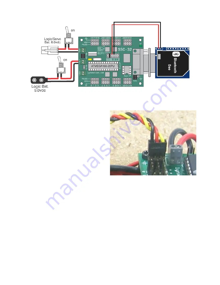
Figure 7. SSC-32 - Bluetooth Wiring
Step 8. Plug the Servos In.
Plug the servos into the SSC-32 as shown in
figure 9 with the yellow signal wire towards the
inside of the board. Simply plug in the servo
associated with the function to the
corresponding pin (see step 9). Once again, be
sure the black wire is near the outside of the
board and the yellow wire is near the center of
the board as shown in figure 8. Proper cable
routing can be done later.
Figure 8.
Step 9. Servo Connections
Double check your connections against the figure below. Be sure that red wires go to positive (+)
and black wires go to negative (-). Also be sure that your jumpers are connected the exact same
way as detailed below. Note that the VL=VS jumper on the SSC-32 is removed, as are the Tx and
Rx jumpers. Depending on the configuration and code, you may also need to change the baud
rate jumpers. The sample code for the BotBoarduino uses 38.4, whereas in order to use the
Bluetooth module, the Baud rate needs to be set to 9600. Note that the wiring from the SSC-32's
Tx / Rx pins to the BotBoarduino's pins are NOT in line - the red / center / power pin needs to be
removed and connected to pin 12 on the BotBoarduino.


