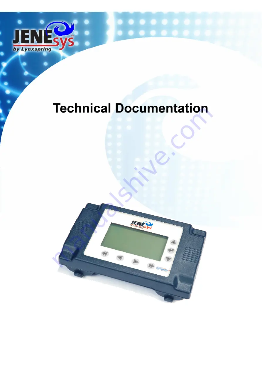
background image


JENE-PCLCD-R Installation Guide 


Summary of Contents for KANEsys JENE-PCLCD-R

Page 1: ...JENE PCLCD R Installation Guide ...

Page 2: ...n or the information contained therein is at the risk of the user Documentation may include technical or other inaccuracies or typographical errors Lynxspring reserves the right to make changes in this document without prior notice and the reader should in all cases consult Lynxspring to determine whether any such changes have been made The information in this publication does not represent a comm...

Page 3: ... OPTION CARD 8 3 INSTALLING THE SHROUD 10 4 MOUNTING THE TRIM RING 11 5 MOUNTING THE LCD ON DIN RAIL 13 6 MOUNTING WITH LCD EYELETS 14 7 POWER OPTIONS 15 8 UN INSTALLING THE JENE PCLCD R 17 9 LISTING OF KIT AND REPLACEMENT PARTS 18 10 TECHNICAL DATA 20 11 RETURNING A DEFECTIVE UNIT 21 12 CERTIFICATIONS 22 Federal Communications Commission FCC 22 RoHS CompliantDeclaration of Conformity 22 Declarati...

Page 4: ... a fully functioning unit Refer to the JENEsys PC Series LCD R Operators Panel Manual for this information These are the main topics included in this document 1 LCD Application and Kit Review page 5 2 Installing the Communication Option Card page 8 3 Installing the Shroud page 10 4 Mounting the Trim Ring page 11 5 Mounting the LCD on DIN Rail page 12 6 Mounting with LCD Eyelets page 13 7 Power Opt...

Page 5: ... JENE is 24Vac at 50 60 Hz if using JENE PC PWR UN 120 Vac at 50 60 Hz if using JENE PC WWPM 120 Disconnect power before installation or servicing to prevent electrical shock or equipment damage Make all connections in accordance with national and local electrical codes Use copper conductors only To reduce the risk of fire or electrical shock install in a controlled environment relatively free of ...

Page 6: ...NE PC LCDCARD qty 1 3 Shroud for mounting onto the base of the JENE JACE controller LCD R S qty 1 JENE PCLCD R Remote is used to mount the LCD interface remotely from the JENE JACE controller greater then 50ft and up to 4 000 ft it includes 1 LCD Interface JENE PCLCD R qty 1 2 RS 485 converter kit LCD R RS485 qty 1 3 Trim ring for mounting on a panel LCD R TR qty 1 4 Power supply with 2 1mm barrel...

Page 7: ...t port is an RS 232 port using a DB 9 plug male connector To the right of this is a two wire with shield isolated RS 485 port using a screw terminal connector plug A green receive LED and yellow transmit LED are provided for each serial port These LEDs are located on the bottom board on the opposite side of the serial connectors These LEDs are labeled on the board COM 1 COM2 and are not visible wi...

Page 8: ... 232 and RS 485 ports see figure 2 on page 8 Labels COM1 and COM2 correspond to the software configuration of the COM ports LEDs show the transmit and receive information for the serial ports and optional modem Note You must remove the cover to the serial port LEDs The yellow transmit LED indicates that the JENE is sending data out the serial port over a communications line to a connected device T...

Page 9: ...ve the JENE JACE controller cover To do this select and press in the four tabs on both ends of the unit and lift the cover off Retain the cover in case the JENE PC LCDCARD Housing Cover must be removed at a later date Step 3 Remove the battery and bracket assembly by taking out the four screws holding it in place setting the screws aside for later Unplug the battery from the connector on the JENE ...

Page 10: ...Step 8 Plug the battery cable into the battery connector on the JENE JACE controller Please refer back to Figure 2 for location Step 9 Set the battery and bracket assembly back over the card slot with the mounting holes aligned with the standoffs The cable should be between the end plate if mounting onto the controller with a shroud and the edge of the battery between the standoffs Step 10 Place t...

Page 11: ...o do this select and press in the four tabs on both ends of the unit and lift the cover off Step 3 Install the communication option card per section 2 Step 4 Plug the cable from the communication option card to the JENE PCLCD R interface device Press the LCD on button to power the LCD from the communication option card Note Note Upon powering the LCD the LCD will remain on and if rebooted it will ...

Page 12: ... x x toggle bolts OR Secure the trim ring to the panel using two 1 4 bolts four 1 4 nuts and min 8 of NS35 7 5 35mm x 7 5mm slotted DIN rail Place the bolts through each end of a DIN rail slot that is extending beyond the LCD Thread a nut on each bolt and tighten the bolt against the panel while tightening the nut against the DIN rail This provides a secure method of mounting the LCD by creating p...

Page 13: ... currently not labeled To power the LCD and LCD R RS485 component use a wall wart and connect the barrel plug to the LCD R RS485 component and then plug the wal wart to a power supply Figure 6 Step 5 Finally connect the RJ11 cable to the LCD press and hold the power button to turn it on Then place the LCD into the trim ring by simply snapping it into the trim ring using the four taps Figure 7 ...

Page 14: ...ed and then shipped Step 1 Securely install the DIN rail using at least two screws near both ends of the rail Step 2 Push down the plastic locking clips Step 3 Position the LCD on the rail tilting to hook DIN rail tabs over one edge of the DIN rail Figure 8 Step 4 Push down and in on the LCD to place the other edge of the LCD onto the DIN rail Step 5 Push the plastic locking clips back to the up p...

Page 15: ...ts on the backside that can be used to hang the LCD Step 1 On the subpanel mark the locations of the screws to be 4 25 apart center to center Step 2 Install screws that have heads no larger than 1 4 in diameter Step 3 Place the LCD such that the screws insert into eyelets on the back of the LCD and slide the LCD down Figure 9 ...

Page 16: ...vailable Rather communication is provided by the controllers on board RS 485 port and power is delivered by the wal wart installed near the LCD and connected to the LCD R 485 component Service Tool When using the LCD as a service tool it is assumed the controller is preprogrammed and has installed the Lynxspring LCD module If a communication option card is installed on the controller the LCD may b...

Page 17: ...ower button When the LCD is powered either by the communication option card or the universal power supply wal wart the LCD will not turn off The LCD may go to a standby or sleep mode but can be returned active by simply activating a button on the face of the LCD When using batteries the LCD will turn itself off after 10 minutes of inactivity Then turn the LCD on by pressing the power button ...

Page 18: ...NE PCLCD R will be re installed at a later time 2 Remove power from JENE JACE controller When screen goes blank strike any key on display to confirm that power is turned off 3 Remove JENE PCLCD R hardware from JENE JACE controller 4 Remove hardware A Remove JENE PCLCD R Housing Cover B Disconnect DB9 Connector 5 Remove battery 6 Remove Blanking End Plate 7 Remove JENE PCLCD R card 8 Screw battery ...

Page 19: ... a hand held or portable service tool Includes 1 LCD Interface Device 1 wal wart power supply 1 RS232 adaptor 1 LCD Communication Option Card and two cables 4 AA batteries are not included LCD R RS485 LCD Interface kit for converting signal to RS485 and extending remote locations up to 4000ft from the JENE JACE controller Replacement Part Number Description JENE PCLCD R Remote LCD Interface Device...

Page 20: ... to the LCD Interface Device Requires 9 MA09M11 to adapt to the RJ11 connection on the LCD and power supply 8101 64101 1 Flat Satin RJ11 Cable for LCD Interface Device TEL 6000 06K RJ11 6 Coiled Black RJ11 Cable for LCD Interface Device TEL 6000 25K RJ11 25 Coiled Black RJ11 Cable for LCD Interface Device MP 5FRJ11STWS 025 25ft Flat Satin RJ11 Cable for LCD Interface Device 8101 64150 50ft Flat Sa...

Page 21: ...ge 15VDC 5 Current LED Backlight Off External 25mA Battery 60mA Current LED Backlight On External 60mA Battery 120mA Operating Temperature 0 F to 50 F Storage Temperature 10 F to 50 F Dimensions Narrow side 3 7 Long side 6 3 Height 1 5 When Mounted on JENE JACE Controller Narrow side 4 0 Long side 7 0 Height 3 8 Capsense Area 7 buttons 2sqin each 1 4sqin Capsense Sensitivity 0 05 lbs sqin Capsense...

Page 22: ...ice available for any of the JENE PCLCD R series products Prior to returning the unit contact Lynxspring to obtain a return material authorization RMA number and other instructions For proper credit on in warranty unit ship the defective module to Lynxspring within 30 days provide information below RMA number provided by Lynxspring Product model Lot Serial numbers and Date Code Nature of the defec...

Page 23: ...omply with the limits for a Class A computing device pursuant to Part 2 Subpart J Part 15 Subpart B of the FCC Rules which are designed to provide reasonable protection against such interference when operated in a commercial environment Any unauthorized modification of this equipment may result in the revocation of the owner s authority to continue its operation RoHS Compliant ...

Page 24: ...et EN55022 Radio Disturbance Conducted Emission Compliant Class B EN55022 Radio Disturbance Radiated Emission Compliant Class B 2006 A1 2007 Measurement control and laboratory use EN55024 Immunity IEC 61000 4 2 Electrostatic E S D Discharge Immunity PASS Criteria B IEC 61000 4 3 Radiated RF Electromagnetic Field Immunity PASS Criteria A IEC 61000 4 4 Electrical Fast Transient Burst Immunity PASS C...

Reviews: