
JENE-PCLCD-R Installation Guide
©2010 Lynxspring. All rights reserved.
Page 6
6. 25 foot coiled cable (TEL-6000-25K-RJ11; qty 1)
•
LCD-R-RS485; is a kit that includes everything needed to power and convert an RS-
485 signal when the LCD is mounted greater than 50ft from the
JENE
/JACE
controller; it includes -
1. RJ11 to 9pin male RS-232 adaptor connected to the 9-pin RS-232 port of the
RS-485/RS-232 converter (9-MA09M11; qty 1)
2. RS-485/RS-232 converter (485SD9TB; qty 1)
3. One foot flat satin cable (8101-64101; qty 1)
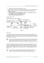
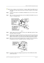
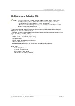
Communication Ports
J EN E bot t om si de ( c over r e m oved )
Figure 1
Serial Ports
There are two serial ports on the JENE base unit. Each has a UART capable of operation up to
115,200 Baud. At the bottom of the board (see Figure 1), the left port is an RS-232 port using a DB-
9 plug (male) connector. To the right of this is a two-wire with shield, isolated RS-485 port, using a
screw-terminal connector plug.
A green “receive” LED and yellow “transmit” LED are provided for each serial port. These
LEDs are located on the bottom board, on the opposite side of the serial connectors.
These LEDs are labeled on the board (COM 1, COM2) and are not visible with the cover
on.
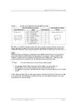
R S - 2 3 2 — An RS-232 serial port using a male DB-9 connector always operates as COM1. You
can use standard DB-9 serial cables with this port. The JENE is a serial DTE device; such another
DTE device (PC, for example) requires a “null modem” cable. If connecting the JENE to a DCE
device (modem, for example), a reverse cable is used. Table 1 provides standard serial DB-9
pinouts.
If a modem option card (JENE-PC-MODEMCARD) is installed, this port becomes
disabled—except if rebooted with the mode jumper in the “Serial Shell” position.


