background image

Page 31 of 51
(North America Edition)

©2019 Lytx, Inc. - Confidential & Proprietary.

Test Event Creation and Upload

1. Key the ignition to ON.

2. (For installations with the Vehicle Interface

Cable only) Plug the Vehicle Interface Cable into
the Device Power Cable.

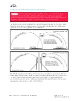
3. Observe the event recorder. The center LED

status light should turn green, then turn off.
The lights then light up from left to right twice,
indicating the device is booting. The center LED
light then turns solid green.

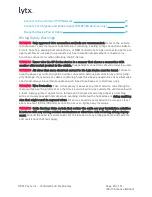
4. Press either blue button on the unit to manually create

an event. The LED status lights will light up green one
by one from left to right until all are lit (lasts ~10
seconds). Confirm this light pattern.

5. Manually upload the event to Lytx:

a. Press and hold one of the blue buttons on the device. The center LED light starts

green, disappears, and then re-appears green. Let go when it re-appears.

b. If upload is successful, all LED status lights will light up one-by-one from left to

right, each light going from blinking to solid green.

c. If upload is unsuccessful (i.e. you receive a different LED status light pattern), the

upload must be attempted again. There are some instances where upload is not
possible due to cellular coverage and the installation is still okay. After success or
failure, the center LED light turns green.

6. Repeat the manual upload process above.

Test Wire Connections and Settings in the Lytx Installation Tool

Prior to Testing

To test wire connections and settings, the Lytx Installation Tool must first be installed
on your laptop. If this hasn't already be done, follow the instructions in "Download and
Install the Lytx Installation Tool" on page 12.

In addition, you must also obtain the correct job file. Obtain this from the client's Imple-
mentation Services Specialist.

Summary of Contents for ER-SF1

Page 1: ...shooting advanced vehicle onboard components including multiplexed circuits Lytx Inc disclaims all responsibility for any damages arising from improper installation and maintenance of the SF Series device This guide is protected as confidential and proprietary information of Lytx Inc Copying and use of this guide for any purpose other than installing SF Series in vehicles of Lytx Inc s customers i...

Page 2: ... Installation 13 SF Series Installation Procedures 15 Mount the Bracket and Event Recorder 15 Review Mounting Location Guidelines 16 Prepare the Mounting Location 18 Attach the Bracket and Event Recorder 19 Connect Electrical Wiring 19 Wiring Safety Warnings 20 Electrical Connection Overview Diagram 21 Wiring and Wire Termination Suggestions 23 Basic Event Recorder Electrical Connections 25 Connec...

Page 3: ...tions 38 Installation Instructions 39 Remote Push Button Installation Procedures 40 Materials 41 Mount the Remote Push Button 41 Assign the Input in the Lytx Installation Tool 41 Maintenance Troubleshooting 42 Maintenance 42 Troubleshooting Installation Issues 42 Troubleshooting Issues After Installation 45 Initiate Diagnostic Mode 46 Troubleshooting in Diagnostic Mode 47 Uninstalling the Device 4...

Page 4: ...e and harness abrasion by properly attaching wires at closely spaced intervals while avoiding contact with sharp edges or doing anything else that might result in exposed wires All wires should be secured with tie wraps at least every one foot 30 cm 300 mm or less Do not over tighten any tie wraps EXPLOSION HAZARD Do not disconnect equipment unless power has been removed and the area is known to b...

Page 5: ...t your supervisor and have the device inspected immediately to correct the issue Whether or not the Lytx Event Recorder is functioning it is the driver s responsibility to maintain vehicle control failure to do so can result in serious personal injury or death or severe property damage CAUTION While cleaning the device or the vehicle cab do not apply compressed air or cleaning solutions such as Wi...

Page 6: ...following two conditions 1 This device may not cause harmful interference and 2 this device must accept any interference received including interference that may cause undesired operation This Class B digital apparatus complies with Canadian ICES 003 Cet appareil est conforme aux normes RSS exemptes de licence d Industrie Canada Son util isation est soumise aux deux conditions suivantes 1 Cet appa...

Page 7: ...Video Event Recorder Product Model l ER SF1 DC 6000 001 l ER SF64 DC 6000 001 l ER SF300 DC 6000 030 The product specified above carries the marking by complying with the essential requirements and provisions Conformity is based upon the following standards Manufacturer s Contact Lytx Inc 9785 Towne Centre Drive San Diego CA 92121 USA Phone Number 858 430 4000 Fax Number 858 430 4001 EMC Radio CFR...

Page 8: ...lity for any damages arising from improper installation and maintenance of the SF Series device THIS GUIDE IS NOT A SUBSTITUTE FOR A QUALIFIED TECHNICIAN THE DEVICE SHOULD NOT INTERFERE WITH THE VEHICLE S COMPUTER SYSTEMS The SF Series device interfaces with the vehicle s computer systems to capture data for safety analysis However it should not interfere with any of the vehicle s computer systems...

Page 9: ...e vehicle 4 Check for laws or regulations that prohibit objects from being mounted on a vehicle s windshield or other locations in a vehicle You are responsible for complying with such laws and regulations and Lytx Inc does not accept responsibility for your failure to do so 5 Use special tools and safety equipment to avoid serious personal injury and damage to components Materials The following m...

Page 10: ...inline fuses Red and Black wires 5 amp fuses Brown wire 1 amp fuse Tamper Prevention Clip For installations including J1939 and or ActiveVision connections Device Power Cable Vehicle Interface Cable with inline fuses Red and Black wires 5 amp fuses Brown wire 1 amp fuse J1939 CAN Coupler Only included in kits for J1939 networks Tamper Prevention Clip ...

Page 11: ...ic tape l Tape measure l Marking pen l T 27 security Torx bit l T 8 security Torx bit l Micro USB cable l Vehicle manufacturer recommended tools Consult the vehicle s maintenance service installation and diagnostic guidelines provided by the manufacturer of the vehicle for any additional tools needed Optional Tools The following tools are not required for installation but can be helpful l Cordless...

Page 12: ... 1 Interior facing lens 2 Microphone 3 Ambient light sensor 4 LED status lights 5 Manual record buttons 6 Serial number on side of device 7 Exterior facing lens 8 Micro USB port 9 Device Power Cable port 10 SIM card and SD card port Download and Install the Lytx Installation Tool The Lytx Installation Tool is a software wizard that walks you through device testing step by step at the end of instal...

Page 13: ...cialist System Requirements for the Lytx Installation Tool Before installation ensure your laptop meets these minimum requirements l Operating System Windows 8 or newer l Hard drive space 256 MB l USB port Instructions for Download and Installation 1 Using the Internet Explorer browser log into the DriveCam Online portal In the upper right corner click on Learning Center 2 Go to My Learnings Then ...

Page 14: ...019 Lytx Inc Confidential Proprietary 4 Browse and find the course for Lytx Installation Tool Download Press Register Then press Start 5 Download the installation file to your computer 6 Open the file Follow the prompts to install the tool ...

Page 15: ...ING Before mounting the bracket and event recorder consult the vehicle manufacturer s recommendations and any applicable federal state provincial and local laws that restrict mounting devices on a vehicle s windshield or other locations in a vehicle Mounting the bracket and event recorder consists of these subsections 1 Review Mounting Location Guidelines a Mounting Location Recommendations and Re...

Page 16: ...d span from the outside shoulder of the driver to the outside shoulder of a front seat passenger If possible it should show the lap band of the seat belt 2 Exterior facing Lens View a Should be inside the path of the wiper blades b Should capture a clear view of everything in front of the vehicle beginning as close to the front of the vehicle as possible without cutting off the horizon To use the ...

Page 17: ...ting location The figures below provide guidelines for mounting the event recorder on the vehicle wind shield that work within the regulations set forth by the U S Department of Transportation Federal Motor Carrier Safety Administration FMCSA The FMCSA regulations allow the event recorder to be mounted not more than 100 mm 4 inches below the upper edge of the area swept by the windshield wipers or...

Page 18: ...equivalent area if there is no rear view mirror see below 2 Clean the mounting area again with the Lytx supplied alcohol wipe 3 Wait 2 minutes for the mounting area to air dry before applying the device bracket Do not dry it with a cloth 4 Following the mounting location guidelines above hold the assembly in place and trace the outline of the bracket on the windshield with a marker Make sure the t...

Page 19: ...st the windshield aligned with the marks and make sure it is level b Press the bracket firmly against the wind shield starting at the left and pressing downward to the right 2 Check from outside the vehicle for large air bubbles under the bracket If you find any a Apply additional pressure to the bracket b Slide a pin between the bracket and wind shield to let out the air 3 Wait 10 minutes to allo...

Page 20: ...ure to fuse the power ground and ignition wires can lead to serious personal injury and or prop erty damage If any wires or cables containing fuses fuse boxes need to be cut or otherwise shortened always be certain to replace such fuses fuse boxes or install new ones WARNING Wire Protection Take all necessary measures to protect all wire runs through a metal surface with a grommet or other device ...

Page 21: ...Page 21 of 51 North America Edition 2019 Lytx Inc Confidential Proprietary Electrical Connection Overview Diagram For standard power only installations ...

Page 22: ...Page 22 of 51 North America Edition 2019 Lytx Inc Confidential Proprietary For installations with J1939 and or ActiveVision connections ...

Page 23: ...le circuit fuses is prohibited 2 Use ONLY 16 gauge automotive primary wire to connect to automotive circuits Specialty wire might be superior when used in its native environment but not in the automotive field For example Teflon wire is intended for high heat conditions but should never be used for connections of the event recorder in the vehicle 3 For all connection methods do not leave any expos...

Page 24: ... make sure to test with a meter that the circuits only share the hot leg of the fuse receptacle to ensure the circuits are separately fused If installed backwards a fuse tap will compromise the original circuit Below is one example Refer to the Fuse Taps Add A Circuits Suggestions section below for more inform ation 8 Quick slide spade connectors Quick slide spade connectors may be used only if th...

Page 25: ...ary options Good slots l power mirrors l HVAC controls Slots to avoid l control modules ECM BCM TCM etc l lights headlights taillights brake hazards l airbags l horn l fuel pump Basic Event Recorder Electrical Connections A minimum of three connections are required for the event recorder to function These leads are found on the Vehicle Inter face Cable Non ECM Device Power Only Cable terminating a...

Page 26: ... gauge wire is often the best choice Connect the BROWN WIRE to 12V 24V Power Source that s IGNITION SWITCHED CAUTION This is a fused connection Do NOT cut off or remove the inline fuse CAUTION The brown wire to a 12V or 24V power source that is ignition switched is important to ensure the event recorder can identify when the ignition is switched on and off and to control the event recorder s Hiber...

Page 27: ...ds to the vehicle as shown in the Electrical Connection Overview Diagram on page 21 Be sure to follow the parameters for each wire detailed above Connect to the Vehicle J1939 Network You may connect to the vehicle J1939 network with the CAN Coupler a coupling device This device uses inductive technology to allow the event recorder to read the data on the J1939 network without any puncture cut or s...

Page 28: ...ocations to find turn signal and brake inputs l Check with the vehicle manufacturer to determine if brake data is reported on the J1939 vehicle network Brake data is reported on most vehicles with J1939 vehicle networks manufactured since 2008 To install ER SF300 devices 1 Connect one of the remaining input wires on the Vehicle Interface Cable to the left turn signal input Typically the white wire...

Page 29: ...cturer for the location of any airbag sensors and systems and restrictions that may apply CAUTION Before proceeding you may need to remove the window and door trim to route the cable underneath These typically snap on and off using special clips In vehicles with side and curtain airbags the clips are often one time use and may need to be replaced after removal Please refer to the vehicle service m...

Page 30: ...tucked away and secured so that it cannot come loose Lytx recommends using cable ties at least every foot or as necessary along the route of the cable to secure it in place Run Testing and Complete Installation Testing is important to make sure the device is connected to the vehicle systems properly and that no active faults exist in the vehicle system Completion of the installation consists of th...

Page 31: ...D light starts green disappears and then re appears green Let go when it re appears b If upload is successful all LED status lights will light up one by one from left to right each light going from blinking to solid green c If upload is unsuccessful i e you receive a different LED status light pattern the upload must be attempted again There are some instances where upload is not possible due to c...

Page 32: ...urements ER SF300 devices only While testing in the Lytx Installation Tool you must take and enter the measurements below Measurements must be entered in whole centimeters cm Tip If you re measuring in inches in convert to cm using of in x 2 54 of cm Convert any fractional inches to decimal first before calculating the cm 1 Vehicle Width Distance between the outer sides of the front tires 2 Camera...

Page 33: ...status lights turn blue hold for about 30 seconds After they light up let go of the button 2 Immediately press and hold the blue button again for up to 45 more seconds First the device s center LED light turns green Then all 7 LED lights turn blue When they turn blue let go of the button 3 Verify the LED status light sequence a First all lights turn off b The center LED light turns green c All LED...

Page 34: ... device but prior to any operation of the vehicle check all vehicle system lights signals and any other devices such as electronic log devices systems or CB radios to make sure they are working properly Minimum checks should include the following consult the vehicle manufacturer s service manual for additional checks that must occur 1 Constant power Ensure the event recorder is powered when the ig...

Page 35: ... to Drive then Reverse and then back to Park Verify that there are no new error codes or Check Engine lights 7 Test the other vehicle components on the power circuit of the SF Series device to confirm their functionality especially if the circuit is shared 8 Verify and diagnose all active faults in the vehicle system other devices and the SF Series device prior to completing the installation 9 Pla...

Page 36: ...l The recommended Standard Mounting Bracket is not feasible in the specific vehicle OR l Windshield mounting is restricted in the juris diction Materials Provided l Overhead Mounting Bracket l Screws NOT provided Drill Attach the Overhead Mounting Bracket and Event Recorder Mounting Location Warnings When selecting the mounting location heed the following warnings l Follow the guidelines specified...

Page 37: ...e sure the lens is in the path of the wiper blades c Make sure the interior facing lens cannot be blocked by any nearby objects Rotate mirrors sun visors and other objects if necessary d Make sure the mounting surface is solid can be safely drilled and the bracket attached securely with screws 3 Mark the position of the bracket and pre drill the screw holes Be careful not to drill or screw into wi...

Page 38: ...ions for installation Materials Provided Extended Mounting Arm NOT provided l Four 4 10 screws Screw length may vary by vehicle but must be long enough to ensure a secure mount l Screwdriver l T 27 security Torx bit l Zip ties l Pen OR pencil Mounting Arm Overview The Mounting Arm may be mounted in a variety of locations due to its versatile design comprised of rotating bracket casing and pivoting...

Page 39: ...g Bracket is not feasible Installation Instructions WARNING Do not extend the Mounting Arm s length beyond its intended design This causes instability which may result in excessive non events being recorded WARNING The Mounting Arm must be oriented vertically straight up or down for adequate stability WARNING When selecting the mounting location check that the mounting surface can be safely drille...

Page 40: ...er socket 6 Attach the base securely to the marked position Pre drill the screw holes Then screw the base into the marked position 7 Re attach the Mounting Arm to the base 8 Pivot rotate the assembly until the event recorder is in the desired position Then tighten the screws Make sure the assembly is firmly secured 9 The Device Power Cable must be secured to the Mounting Arm with zip ties After yo...

Page 41: ...nect it to the Vehicle Interface Cable Non ECM Device Power Only Cable Refer to the Electrical Connection Overview Diagram on page 21 4 Mount the button into the hole Secure it from the inside with the hex nut Assign the Input in the Lytx Installation Tool To complete installation of the Remote Push Button its input must be properly assigned in the Lytx Install ation Tool To assign the input 1 Go ...

Page 42: ...or wear Electrical cables that are pinched or frayed may be found on vehicles where the electrical connection was incorrectly installed Further cables and wires may become worn or exposed over time due to contact with sharp edges or objects and when impacted by other electronic work mechanical work or installations If any actual or potential cable wire damage is detected necessary repairs should b...

Page 43: ... vehicle fuse for that circuit The Model and Device Serial Number do not appear in the Lytx Install ation Tool There may be an issue with Windows Firewall Plug the device in again and verify that the Lytx Installation Tool is allowed through Windows Firewall The Lytx Connection is not being detected in the Lytx Installation Tool Perform a forced check in Hold one of the blue buttons for 10 seconds...

Page 44: ...he Yellow wire is on the CAN_HI Y side of the Coupler and the Green wire is on the CAN_LO G side J1939 Connections Ensure that the CAN Coupler connector is fully engaged J1939 Connections The CAN Coupler may not have been placed on the J1939 backbone but on a stub Try moving the Coupler to a different location The turn signal or brake inputs aren t being detected in the Lytx Install ation Tool Ver...

Page 45: ... Non ECM Device Power Only Cable may be damaged Check the entire length of the wire for damage cuts Fix any issues The SF Series device does not come out of Hiberna tion mode when the igni tion is activated There may be an issue with the brown wire connection Check the wire for damage Gauge the wire with a voltmeter for 12V 24V with the ignition on Check the vehicle fuse for that circuit The SF Se...

Page 46: ...he device until the 3 center LED status lights turn blue hold for about 30 seconds After they light up let go of the button 2 Immediately press and hold the manual record button again for up to 45 more seconds until all 7 LED status lights turn blue After they light up let go of the button At this point the SF Series will begin rebooting LED Status Light Sequence Reboot 1 As the device shuts down ...

Page 47: ...ides the status of a different component of the device as shown below Please note l All LED status lights will turn red to start Each LED will turn green when if the corres ponding feature is confirmed as working properly l In Diagnostic Mode the LED status lights will not turn any colors other than green or red Except for LED 2 which may also turn yellow l The device will stay in Diagnostic Mode ...

Page 48: ... Only for installations including vehicle network connections Start the vehicle Ensure the vehicle is running J1939 Connections The wires may be reversed over the CAN Coupler Ensure that the Yellow wire is on the CAN_HI Y side of the Coupler and the Green wire is on the CAN_LO G side J1939 Connections Ensure that the CAN Coupler connector is fully engaged J1939 Connections The CAN Coupler may not ...

Page 49: ...to remove the cable underneath These typically snap on and off using special clips In vehicles with side and curtain airbags the clips are often one time use and may need to be replaced after removal Please refer to the vehicle service manual for information CAUTION Do not try to pull or pry the bracket off the windshield Doing so may cause damage to the windshield Materials l Torx wrench OR screw...

Page 50: ...nd down the A pillar WARNING Be very careful working around vehicle airbags Please refer to the vehicle s service manual for information 7 Locate the existing connection points in the vehicle fuse panel Follow the path of the harness or consult the vehicle manufacturer s manual to find the fuse panel Typically the panel is located underneath the dashboard on the driver s or passenger s side 8 Disc...

Page 51: ...n optional CAN Coupler remove the cap on the CAN Coupler Remove the wires inside Contact Technical Support For troubleshooting support please contact the Lytx Technical Support Center at 925 732 4246 or email support lytx com Installation Support Hours l Monday Friday 7am 8pm EST l Saturday Sunday 8am 6pm EST ...

Reviews: