- 5 -
1.4.4. Binocular attachment
Additional (tube inside) lenses and Schmidt prisms are installed in the binocular
attachment
2
.
Setting up of an interpupilary distance to fit eye base of an observer is carried out by
bringing together or pulling apart of eyepiece tubes
Б
The binocular attachment 2 is
fastened to the body
Г
using bayonet joint with fixture by a screw 11. In operation
condition the screw shall be tighten to stop.
The interchangeable eyepieces are installed in the eyepiece tubes.
1.4.5 Microscope table
On the stand
16
of the microscope table there is fixed the optical head by the fixation
handle that always should be tighten. which should always be tightened.
The microscope focusing to an object is made by handles 13 turning of the optical head
relative to the microscope table along the guide “dovetail” (Fig. 1).
Attention! Never turn the handle 13 in mutually antithetic directions.
To prevent an accident dropping of the optical head of the microscope on the stand
there is the stopper 15 fixed in the required position using a clamping screw. The table
has a round window where the plate
12
, two holes for the clamps
10
and three holes for
the substage ST-12 are installed in. ST-12 is not a deliverable item of this microscope
and is procured separately. One of the side of the plate 12 is painted in white color and
intended for viewing at dark objects, the other one is black that intended for viewing of
light objects.
1.4.6. Illuminator
The illuminator 4 is installed in the slot of the bracket 9 and allows illuminating of an
object with different sides. The bracket 9 is fixed in a proper position with help of screw
ring 8.
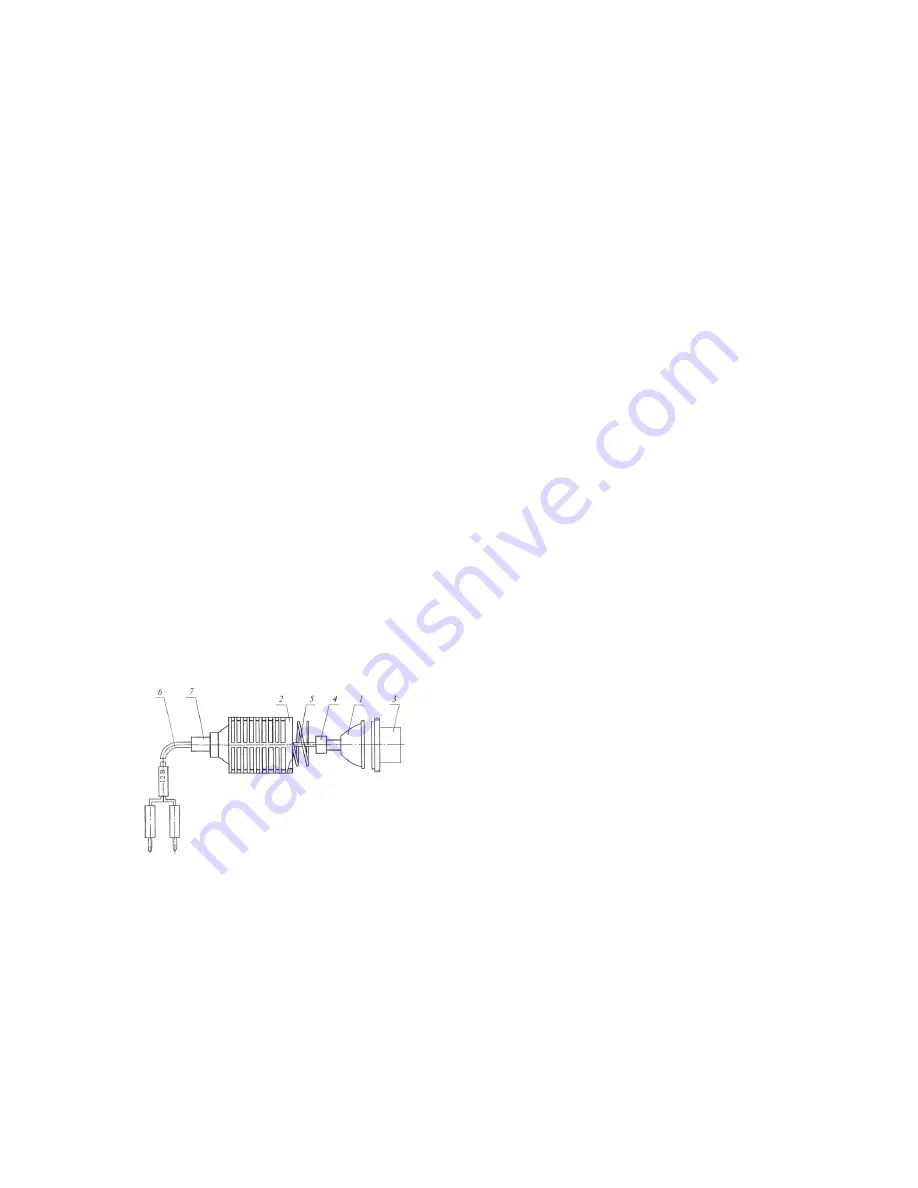
A disassembled illuminator is presented in Fig. 2 and consists of lamp
1
, body
2
, seat
flange
3
, chuck
4
, spring
5
, cord
6
, and bush
7.
Figure 2 – Illuminator
- 6 -
The deliverables of the microscope composes a light filter that is screw jointed to the
seat flange
3
of the illuminator.
The illuminator power can be controlled changing lamp power voltage.
1.4.7. Power supply unit
The power of the illuminator lamp is provided through the power supply unit
6
(Figure
1) from AC points of 220 V using the cord with the plug of the side ground contact. The
cover of the power supply unit has a connecter of 12V for the illuminator switching on
(by means of two prongs). The side walls of the power supply unit have a toggle switch,
a lamp voltage regulator handle, holders of safety devices (of fused plugs) of 1.0A and
3.15A.
2 SAFETY PRECAUTIONS
2.1 The microscope is intended for indoor operation under conditions of absence of
increased electrical danger. The conditions increasing the mentioned danger are:
a) increased humidity and dustiness of air;
b) current-conducting floor: metal, brick, reinforced-concrete;
c) temperatures above 40
0
C.
2.2 Regularly, before connecting the microscope to the power mains, the safety of the
cord insulation, power supply unit and illuminator should be checked.
2.3 The lamp and the fused plugs (safety devices) are required to be changed when the
illuminator and the power supply unit are switched off.
3 PREPARATIONS FOR USE
If the instrument is delivered indoors from cold, unpack it six hours after bringing it
inside.
After unpacking the instrument is needed to be prepared for the operating and assemble
the microscope to the status noted in Figure 1.
In doing that the binocular attachment 2 is to be jointed to the body
Г
of the zoom
system using the crew 11.
The selected eyepieces 10
x
and 20
x
are installed in the tubes
Б
binocular attachment
priory having set the zero diopter value in scale of the eyepiece.
The illuminator 4 is installed in the slot of the bracket 9 and is connected via two prongs
to the power supply unit 6. The plate 12 and two clamps 10 are positioned at the
operating table 5.


