MM-010539-001, Rev. P6G
47
6.
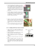
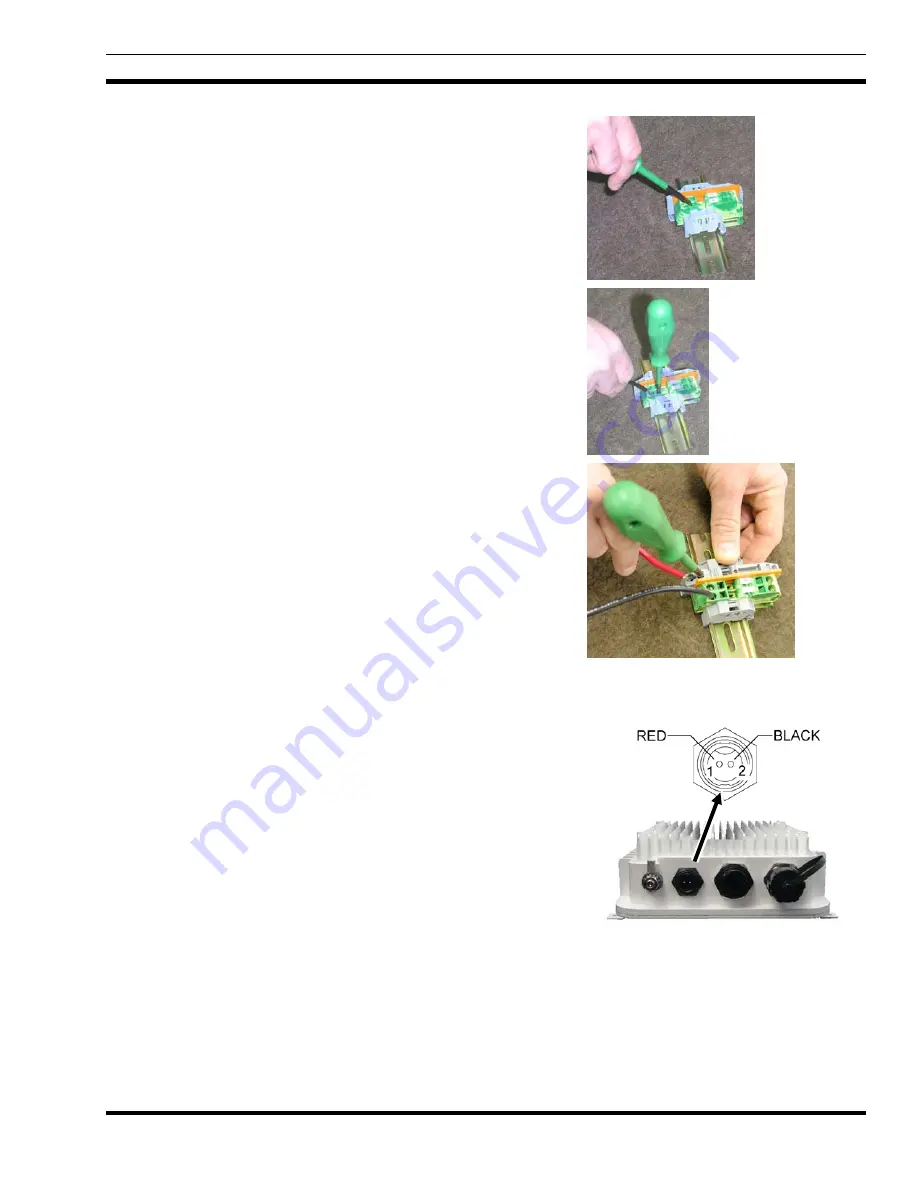
The Fuse Distribution Rail Assembly has two green-
yellow Grounding Blocks. Each Grounding Block has
two wire-clamps with associated wire-clamp release
slots. As shown in the photo at the right, insert a #1 or
#2 flat-blade screwdriver completely into one of the
wire-clamp release slots. Insert the screwdriver until it is
captured in a vertical position as shown in the photo in
the next step.
7.
Insert the stripped end of the black wire fully into the
wire-clamp beside the screwdriver, and then remove the
screwdriver to lock the wire in the clamp. The adjacent
Grounding Block is electrically connected together, so
this black wire grounds both blocks.
8.
Prepare to connect the 10-AWG red wire from the Fuse
Holder at the vehicle battery to the Fuse Block of the
DIN rail assembly by cutting off the excess length and
stripping the end. Leave enough wire length for a service
loop.
9.
As shown in the photo at the right, connect the 10-AWG
red wire to the Fuse Block’s supply-side wire-clamp.
8.3.1.3 Installing the DC Power Cable to the Client
1.
Prepare a short 12 to 14 AWG red and black wire (not
supplied) to run between the fuse block and the Client’s
DC power connection.
2.
Install a Conxall pin on one end of the red wire. Install
the red wire into Pin 1 of the Conxall connector.
3.
Install a Conxall pin on one end of the black wire.
Install the black wire into Pin 2 of the Conxall
connector.
4.
Assemble the shell and strain relief to the connector
body.
5.
Mate the assembled connector to the Client’s 2-pin
power connector as follows: Visually align the key and
firmly push and turn the outer locking ring clockwise
until it stops. A click will be sensed to confirm proper
mating.

