MM-010539-001, Rev. P6G
6
TABLE OF FIGURES
Page
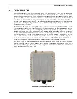
Figure 4-1: VIDA Broadband Client .................................................................................................... 21
Figure 4-2: VIDA Broadband Wireless Broadband Video and Data Services.................................... 22
Figure 4-3: VIDA Network Solution................................................................................................... 23
Figure 4-4: VIDA Broadband Network............................................................................................... 24
Figure 4-5: Network Diagram of Small VIDA Broadband System..................................................... 25
Figure 4-6: VIDA Broadband Client Interface Diagram ...................................................................... 28
Figure 6-1: Mounting the VIDA Broadband Client ............................................................................ 33
Figure 7-1: VIDA Broadband Client Antenna with External Lightning Protection............................. 38
Figure 7-2: Mounting a Directional Antenna to the VIDA Broadband Client .................................... 39
Figure 8-1: Mobile Mounting Bracket (FM-010668).......................................................................... 43
Figure 11-1: Tyco/Electronics Industrial Circular Ethernet Connector Plug Kit (1738607-2) ........... 52
Figure 11-2: Cable Preparation............................................................................................................ 53
Figure 11-3: Cable Preparation Continued .......................................................................................... 54
Figure 11-4: Termination Requirements ............................................................................................. 55
Figure 11-5: Assembly Detail.............................................................................................................. 56
Figure 11-6: Tyco/Electronics LC Fiber Optic Connector Plug Kit (1828618-1)............................... 57
11-7: Fiber Optic Connector Assembly............................................................................................... 58
11-8: Protective Connector Cover Installed ........................................................................................ 59
TABLE OF TABLES
Page
Table 1-1: MPE Minimum Distance Calculation for Mobile Client Installations............................... 10
Table 1-2: MPE Minimum Distance Calculation for Fixed Client Installations Using High Gain
Antennas............................................................................................................................ 15
Table 2-1: Glossary of Terms.............................................................................................................. 17
Table 4-1: Recommended Fixed Station Antennas* ........................................................................... 30
Table 7-1: Power Connector Pin Configuration for AC Voltage Sources........................................... 37
Table 7-2: Power Connector Pin Configuration for DC Voltage Sources........................................... 37
Table 8-1: Fuse Distribution Rail Kit .................................................................................................. 42
Table 8-2: Power Connector Pin Configuration for DC Voltage Sources........................................... 43


