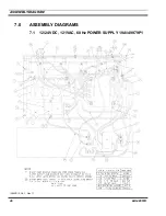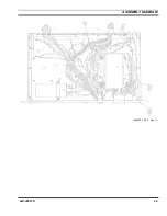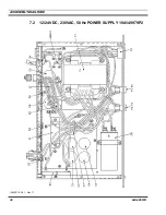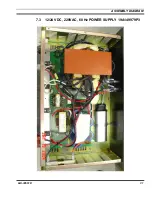
PARTS LIST
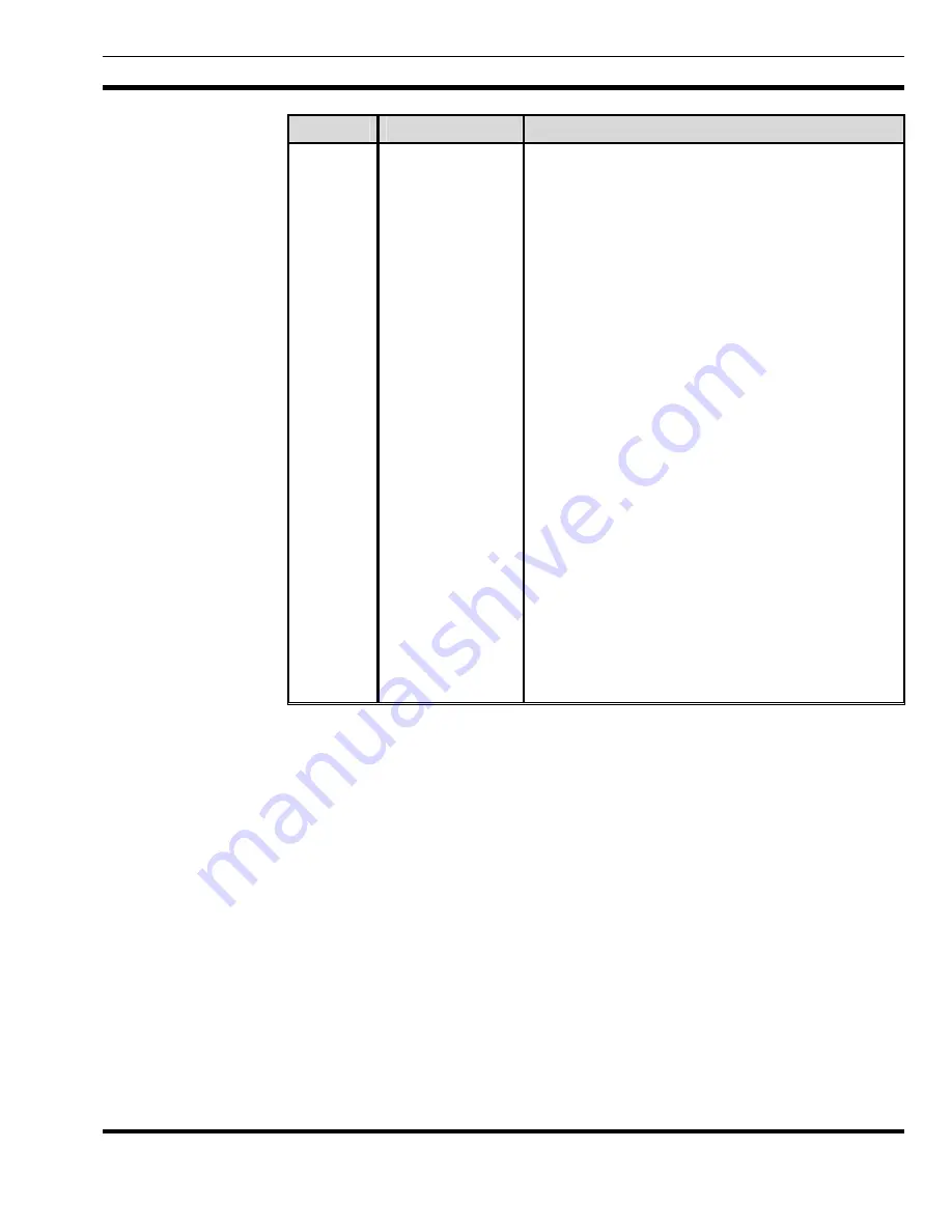
SYMBOL
PART NUMBER
DESCRIPTION
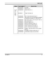
83310240000
Insulator.
81622046700
Rivet (Qty. 2).
E2, E7
and
E11
83322045500
Perm Stud; (Qty. 3).
TB1
thru
TB8
820130618
Faston Tabs (Qty. 8).
81622041501
Nut: Printed Wire Board (Qty. 7).
81622041502
Nut: Bottom cover, Ground Stud and Capacitor
U9 Bracket and Resistor R1 bracket (Qty. 4).
81622041503
Nut: #10-32; goes on, E2, E7 and E11 (Qty. 3).
81622041504
Nut (Transformer T1)
81505065600
Bracket (Capacitor C9).
81622044600
Screws: Bracket for C9 (Qty. 2).
81622009003
Screws: Rear of chassis (Qty. 3).
81622046400
Screw: Fastens top cover (Qty. 8).
81622049500
Screw: Fastens front panel (Qty.5).
81622010305
Washer: Goes with screws in rear of chassis
(Qty. 3).
81622043200
Standoffs, Printed Wire Board (Qty. 7)
81572067900
Terminal Boot (Goes over end of C9).
LBI-38551D
27
Summary of Contents for P5100 Series
Page 11: ...CIRCUIT ANALYSIS Figure 4 3 60 Hz Power Supply 19A149979P3 LBI 38551D 11...
Page 29: ...ASSEMBLY DIAGRAM 289PS15 Sh 2 Rev T LBI 38551D 29...
Page 31: ...ASSEMBLY DIAGRAM 7 3 12 24 VDC 220VAC 60 Hz POWER SUPPLY 19A149979P3 LBI 38551D 31...
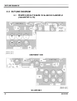
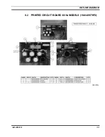
Page 33: ...OUTLINE DIAGRAM 8 2 PRINTED CIRCUIT BOARD 60 Hz MODELS 19A149979P2 289PS16 LBI 38551D 33...
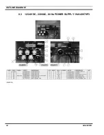
Page 34: ...OUTLINE DIAGRAM 8 3 12 24 VDC 220VAC 60 Hz POWER SUPPLY 19A149979P3 289PS25 34 LBI 38551D...
Page 36: ...SCHEMATIC DIAGRAM 9 2 POWER SUPPLY 19A149979P2 Model 289PS16 289PS16 Rev A 36 LBI 38551 Rev D...


