IMPORTANT SAFETY INFORMATION
2.0 IMPORTANT SAFETY INFORMATION
The following conventions are used throughout this manual to alert the user to general
safety precautions that must be observed during all phases of operation, service, and
repair of this product. Failure to comply with these precautions for with specific warnings
elsewhere in this manual violates safety standards of design, manufacture, and intended
use of the product. M/A-COM Inc. assumes no liability for the customer’s failure to
comply with these standards
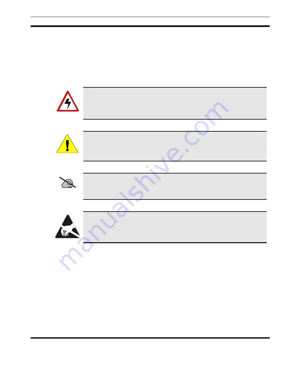
WARNING
The
WARNING
symbol calls attention to a procedure, practice, or the like, which, if
not correctly performed or adhered to, could result in personal injury. Do not proceed
beyond a WARNING symbol until the conditions identified are fully understood or
met.
CAUTION
The
CAUTION
symbol calls attention to an operating procedure, practice, or the like,
which, if not performed correctly or adhered to, could result in damage to the
equipment or severely degrade the equipment performance.
NOTE
The
NOTE
symbol calls attention to supplemental information, which may improve
system performance or clarify a process or procedure.
The
ESD
symbol calls attention to procedures, practices, or the like, which could
expose equipment to the effects of
E
lectro-
S
tatic
D
ischarge. Proper precautions must
be taken to prevent ESD when handling circuit modules.
1. SAVE THIS MANUAL - It contains important safety and operating instructions.
2. Before using the product, please follow and adhere to all warnings, safety and
operating instructions located on the product and in the manual.
3. DO NOT expose product to rain, snow or other type of moisture.
4. Care should be taken so objects do not fall or liquids do not spill into the product.
5. DO NOT expose product to extreme temperatures.
6. DO NOT use auxiliary equipment not recommended or sold by the manufacturer. To
do so may result in a risk of fire, electric shock or injury to persons.
7. To reduce risk of damage to electrical cord, pull by plug rather than cord when
disconnecting unit.
8. Make sure the cord is located so it will not be stepped on, tripped over or otherwise
LBI-38551D
5
Summary of Contents for P5100 Series
Page 11: ...CIRCUIT ANALYSIS Figure 4 3 60 Hz Power Supply 19A149979P3 LBI 38551D 11...
Page 29: ...ASSEMBLY DIAGRAM 289PS15 Sh 2 Rev T LBI 38551D 29...
Page 31: ...ASSEMBLY DIAGRAM 7 3 12 24 VDC 220VAC 60 Hz POWER SUPPLY 19A149979P3 LBI 38551D 31...
Page 33: ...OUTLINE DIAGRAM 8 2 PRINTED CIRCUIT BOARD 60 Hz MODELS 19A149979P2 289PS16 LBI 38551D 33...
Page 34: ...OUTLINE DIAGRAM 8 3 12 24 VDC 220VAC 60 Hz POWER SUPPLY 19A149979P3 289PS25 34 LBI 38551D...
Page 36: ...SCHEMATIC DIAGRAM 9 2 POWER SUPPLY 19A149979P2 Model 289PS16 289PS16 Rev A 36 LBI 38551 Rev D...


