30
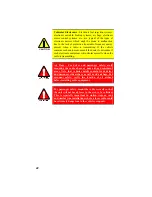
CAUTION
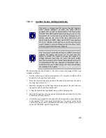
Certain problems might be encountered when accessory
equipment is connected to the ignition or accessory lines
of the vehicle, where these lines can have large filter
capacitors and a leakage path present. If the radio does not
turn off within a reasonable amount of time after the
ignition is turned off, first try a different accessory or
ignition sense pick-up point in the vehicle. Many vehicles
have more than one circuit that is switched by the ignition
switch, and one might be available that does not have
large filter capacitors or a leakage path present.
If a different pick-up point cannot be found, add a 470-
ohm, 1-watt resistor from the ignition sense pick-up point
to ground. This will discharge the capacitor(s) or reduce
the leakage voltage to a low value. Current drain through
this resistor will be minimal (less than 0.03A) when the
ignition is switched on.
10.1.4
Control Cable (Remote Mount Only)
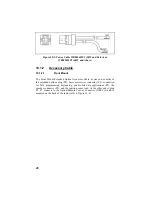
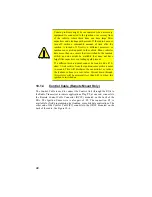
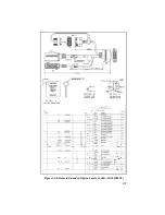
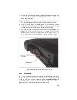
The Control Cable is used to connect the Control Unit (through the RIA) to
the Radio Transceiver in remote applications. Plug P2, at one end, connects to
the Remote Control Cable Connector (RCCC) mounted on the back of the
RIA. The Ignition Sense wire is also part of P2. The connection, P5, is
available for field programming, keyloading, or mobile data applications. The
other end of the Control Cable (P1) connects to the ORCC mounted on the
back of the radio. See Figure 10-6.
Summary of Contents for P5100 Series
Page 1: ...Installation Product Safety Manual MM102342V1 Rev Fp1 Sep 07 M7100IP Series Mobile Radio...
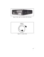
Page 17: ...17 Figure 7 2 Rear Angle View of Radio 110W VHF Shown Figure 7 3 Interface Cables...
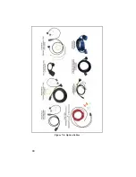
Page 18: ...18 Figure 7 4 Option Cables...
Page 27: ...27 Figure 10 4 Front Mount Extended Option Accessory Cable CA101288V2...
Page 31: ...31 Figure 10 6 Remote Extended Option Control Cable CA101288V4...
Page 64: ...64 Figure 12 3 Dual Radio Configuration Front Remote Mount PC Programming Procedure...
Page 66: ...66 Figure 12 4 Dual Radio Configuration Remote Remote Mount PC Programming Procedure...
Page 67: ...67 Figure 12 5 Dual Radio Control Cable CA101288V10...
Page 71: ...71 NOTES...

