36
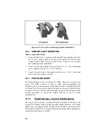
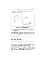
1.
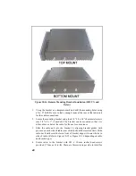
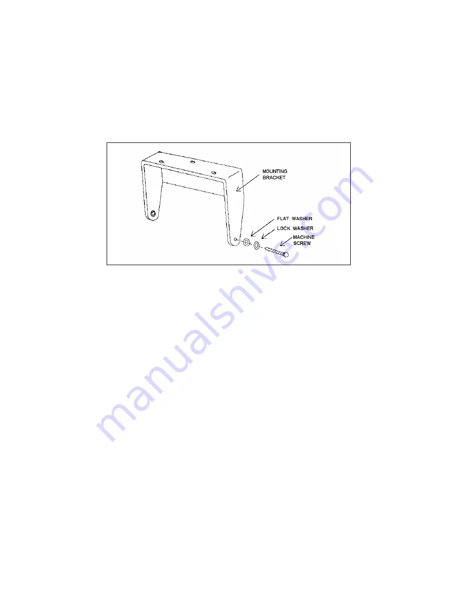
Use the mounting bracket as a template for locating the mounting holes
and mount the speaker as shown in Figure 10-13.
2.
Refer to the applicable installation procedures for connection of the
speaker to the accessory cable.
Figure 10-13: Speaker Mounting Bracket
10.5 MICROPHONE HANGER AND/OR HOOKSWITCH
MOUNTING
The microphone hanger or hookswitch should be mounted in a location
convenient to the operator where it will not interfere with the safe operation of
the vehicle or be a hazard to the vehicle passengers. The hanger and
hookswitch are designed to be mounted with the open end of the mounting
button slot pointed upward. Use the hanger or hookswitch as a template to
mark and drill the mounting holes. Mount the hanger or hookswitch with the
self-tapping screws provided.
10.6 SIREN AND LIGHT
For instructions about installing the Federal Signal Corporation Siren and
Light Kit, refer to the Federal Signal Corporation Installation Instructions
(Federal Systems part number 255287B, rev. B or higher).
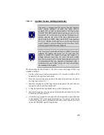
Program the radio to work with the Federal Systems Siren and Light Kit,
using the instructions outlined in the ProGrammer On-Line Help.
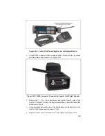
In a remote mount installation, three jumpers must be reconfigured in the
remote control unit. These jumpers are located on the Remote Interface
Adapter (RIA), a PC board in the back half of the unit. To access these
jumpers, the RIA must be removed from the control unit as follows:
Summary of Contents for P5100 Series
Page 1: ...Installation Product Safety Manual MM102342V1 Rev Fp1 Sep 07 M7100IP Series Mobile Radio...
Page 17: ...17 Figure 7 2 Rear Angle View of Radio 110W VHF Shown Figure 7 3 Interface Cables...
Page 18: ...18 Figure 7 4 Option Cables...
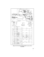
Page 27: ...27 Figure 10 4 Front Mount Extended Option Accessory Cable CA101288V2...
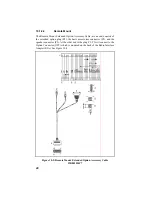
Page 31: ...31 Figure 10 6 Remote Extended Option Control Cable CA101288V4...
Page 64: ...64 Figure 12 3 Dual Radio Configuration Front Remote Mount PC Programming Procedure...
Page 66: ...66 Figure 12 4 Dual Radio Configuration Remote Remote Mount PC Programming Procedure...
Page 67: ...67 Figure 12 5 Dual Radio Control Cable CA101288V10...
Page 71: ...71 NOTES...

