5
1
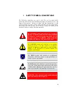
SAFETY SYMBOL CONVENTIONS
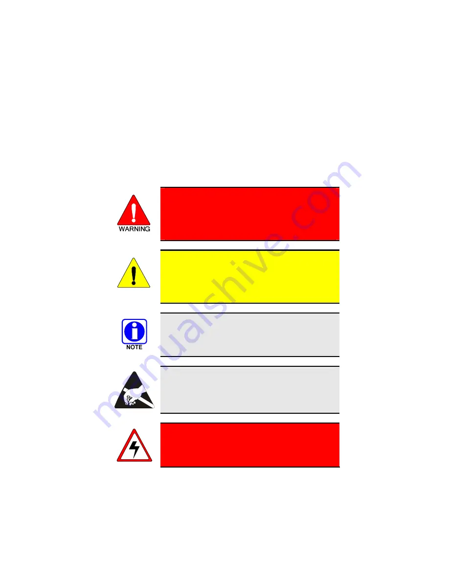
The following conventions are used to alert the user to general safety
precautions that must be observed during all phases of operation, service, and
repair of this product. Failure to comply with these precautions or with
specific warnings elsewhere violates safety standards of design, manufacture,
and intended use of the product. M/A-COM, Inc. assumes no liability for the
customer's failure to comply with these standards.
The WARNING symbol calls attention to a procedure,
practice, or the like, which, if not correctly performed
or adhered to, could result in personal injury. Do not
proceed beyond a WARNING symbol until the
conditions identified are fully understood or met.
CAUTION
The
CAUTION
symbol calls attention to an operating
procedure, practice, or the like, which, if not performed
correctly or adhered to, could result in a risk of danger,
damage to the equipment, or severely degrade the
equipment performance.
The
NOTE
symbol calls attention to supplemental
information, which may improve system performance or
clarify a process or procedure.
The
ESD
symbol calls attention to procedures, practices,
or the like, which could expose equipment to the effects
of
E
lectro-
S
tatic
D
ischarge. Proper precautions must be
taken to prevent ESD when handling circuit modules.
WARNING - The electrical hazard symbol indicates
there is an electrical hazard present.
Summary of Contents for P5100 Series
Page 1: ...Installation Product Safety Manual MM102342V1 Rev Fp1 Sep 07 M7100IP Series Mobile Radio...
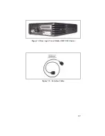
Page 17: ...17 Figure 7 2 Rear Angle View of Radio 110W VHF Shown Figure 7 3 Interface Cables...
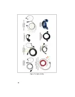
Page 18: ...18 Figure 7 4 Option Cables...
Page 27: ...27 Figure 10 4 Front Mount Extended Option Accessory Cable CA101288V2...
Page 31: ...31 Figure 10 6 Remote Extended Option Control Cable CA101288V4...
Page 64: ...64 Figure 12 3 Dual Radio Configuration Front Remote Mount PC Programming Procedure...
Page 66: ...66 Figure 12 4 Dual Radio Configuration Remote Remote Mount PC Programming Procedure...
Page 67: ...67 Figure 12 5 Dual Radio Control Cable CA101288V10...
Page 71: ...71 NOTES...


