56
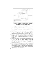
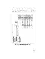
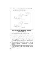
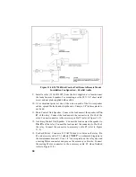
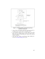
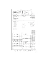
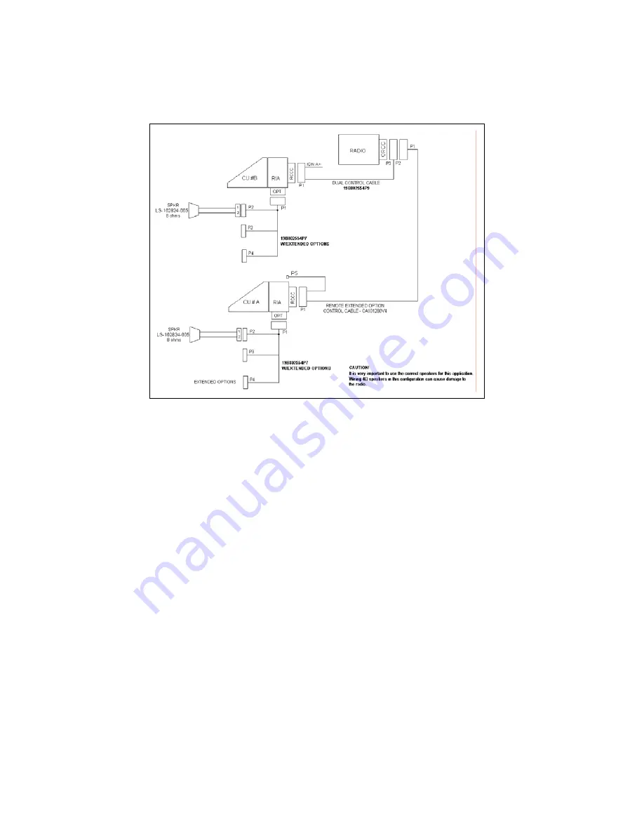
Figure 11-10: M7100 Dual Control Unit Remote/Remote Mount
Installation Configuration – Parallel Audio
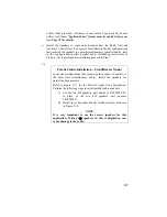
9. Install a relay (19A149299P1) from the kits supplied at a location near
the leads from each speaker. For mounting, use the #8 X 3/4” sheet metal
screw and nut plate supplied with each kit.
10.
At a convenient point cut one of the wires in each of the 2-wire speaker
cables, spread the leads, and strip the ends. Crimp a 1/4” tab receptacle to
each end.
11. Main Control Unit Speaker: Connect the lead nearest the speaker to
Pin
87
of the relay. Connect the lead nearest the connector to Pin 30 of the
relay. Connect connector to the accessory cable P2 (refer to Figure 11-9).
12. Auxiliary Control Unit Speaker: Connect the lead nearest the speaker to
Pin 87A
of the relay. Connect the lead nearest the connector to Pin 30 of
the relay. Connect the connector to accessory cable P2 (refer to Figure
11-9).
13. For Each Relay: Connect a #18 AWG black wire between the relay, Pin
85 and accessory cable P3-1 (labeled
“OUT2”
on schematic diagrams in
the maintenance manual). Use a 1/4” tab receptacle on the relay side and
a mating Molex connector and pins on the accessory cable side. Connect
the mating Molex connector to the accessory cable P3 when finished
(refer to Figure 11-9).
Summary of Contents for P5100 Series
Page 1: ...Installation Product Safety Manual MM102342V1 Rev Fp1 Sep 07 M7100IP Series Mobile Radio...
Page 17: ...17 Figure 7 2 Rear Angle View of Radio 110W VHF Shown Figure 7 3 Interface Cables...
Page 18: ...18 Figure 7 4 Option Cables...
Page 27: ...27 Figure 10 4 Front Mount Extended Option Accessory Cable CA101288V2...
Page 31: ...31 Figure 10 6 Remote Extended Option Control Cable CA101288V4...
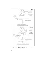
Page 64: ...64 Figure 12 3 Dual Radio Configuration Front Remote Mount PC Programming Procedure...
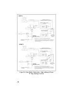
Page 66: ...66 Figure 12 4 Dual Radio Configuration Remote Remote Mount PC Programming Procedure...
Page 67: ...67 Figure 12 5 Dual Radio Control Cable CA101288V10...
Page 71: ...71 NOTES...

