MM102225V1, Rev. B
14
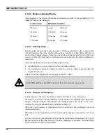
2.2.2.2 Minimum Bending Radius
Always adhere to the minimum bending requirements provided by the manufacturer. For
Andrew Products, the values are:
CABLE SIZE
BENDING RADIUS
1/4-inch
1/2-inch
7/8-inch
1-5/8-inch
1-inch
(25 mm)
1.25-inch (32
mm)
10-inches (250
mm)
20-inches (510
mm)
2.2.2.3 Hoisting
Grips
Hoisting grips provide the means to attach a lifting mechanism to the coaxial cable
without damaging the cable. Each hoisting grip is capable of safely lifting 200 feet of
cable without causing damage. Therefore, one hoisting grip is required for every 200-foot
section of cable. The grips may be left attached to the cable after the cable installation is
completed.
Some situations may require more hoisting grips, such as:
•
An installation to a tower which is on top of another structure.
•
Any installation where the length of cable that must be lifted is greater than the
height of the tower.
In these situations, additional hoisting grips should be ordered.
WARNING
Under
NO
conditions should RF connectors be used to attach a rope or cable.
2.2.2.4 Hangers and Adapters
Coaxial cables on the tower should be secured at intervals of 3 feet (maximum).
Securing 7/8-inch and 1 5/8-inch diameter coaxial cables is accomplished by using either
hangers or hanger-adapter combinations. The hangers secure the cables to the tower
structure by using prepunched holes or attachment adapters.
When the tower structure is prepunched with 3/4-inch holes, snap-in hangers are used
(preferred method).
When the tower is prepunched with 3/8-inch holes, the hanger is secured by a 3/8-inch
bolt.
For towers without prepunched holes, the hangers are attached with adapters. The type of
adapter depends on the type of tower structure. Adapters are available for either angle
tower members or round tower members.
Summary of Contents for P5100 Series
Page 2: ...Installation Manual MM102225V1 Rev B Jul 05 Base Station Tower Site ...
Page 70: ...MM102225V1 Rev B 69 This page intentionally left blank ...
Page 72: ...MM102225V1 Rev B 71 This page intentionally left blank ...
Page 74: ...MM102225V1 Rev B 73 This page intentionally left blank ...
Page 76: ...MM102225V1 Rev B 75 This page intentionally left blank ...
Page 82: ...MM102225V1 Rev B 81 PARAMETER VALUE EXPLANATION password cisco login end buck40sas ...
Page 92: ...MM102225V1 Rev B 91 This page intentionally left blank ...
Page 94: ...MM102225V1 Rev B 93 This page intentionally left blank ...
Page 96: ...MM102225V1 Rev B 95 This page intentionally left blank ...
Page 99: ...MM102225V1 Rev B 98 This page intentionally left blank ...

